 | –≠–ª–µ–∫—Ç—Ä–æ–Ω–Ω—ã–π –∫–æ–º–ø–æ–Ω–µ–Ω—Ç: 24S15.4XW | –°–∫–∞—á–∞—Ç—å:  PDF PDF  ZIP ZIP |

A
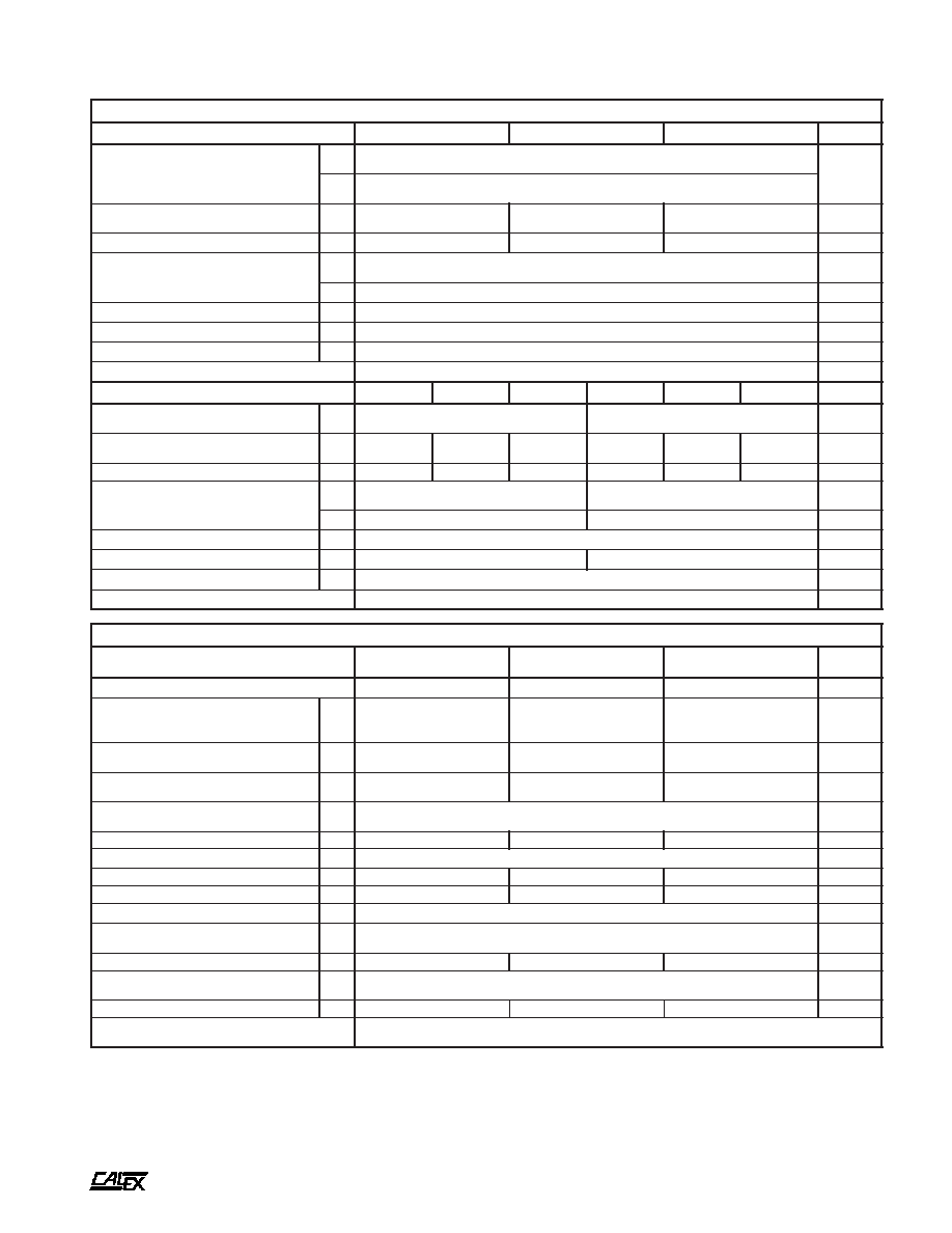
50 to 60 XW Single Series DC/DC Converters
Manufacturing Company, Inc. ∑ Concord, California 94520 ∑ Ph: 925/687-4411 or 800/542-3355 ∑ Fax: 925/687-3333 ∑ www.calex.com ∑ Email: sales@calex.com
1
eco# 041007-1
Features
Lowest Noise Outputs, 50 mV P-P
Maximum
Fully Shielded/Filtered Design
Very Low and Specified Reflected Ripple Current
Low and Specified Input/Output Capacitance
Isolation Voltage Raised to 700 or 1544 VDC as Per
the Requirements of UL1459
Five Year Warranty
Description
These single output converters are designed for wide input
range low noise telecommunications, industrial, and
instrument applications. The wide input range (2:1) is ideal for
battery or unregulated input applications while the low noise
complements even the most sensitive analog circuitry.
These converters are state-of-the art 220 kHz MOSFET
based designs that provide outstanding line and load
regulation with efficiencies exceeding 85%.
The single outputs are regulated by a high loop gain current
mode control method that provides linear regulator type
performance with a true, high efficiency switching DC/DC
topology. The large amount of loop gain also insures excellent
input ripple rejection and line transient response. Remote
output voltage sense, output voltage trim and ON/OFF
functions are also included.
They are protected from output shorts to common by a high
speed pulse-by-pulse digital current limit circuit and a
self-resetting thermal overload protection circuit. The input
and output are overvoltage protected with 1500W transient
suppressor diodes for zero failure rate operation.
As with all CALEX converters the 50/60 Watt XW Single
Series is covered by our standard 5 Year Warranty.
60 Watt Single Series Block Diagram
t
r
a
h
C
n
o
i
t
c
e
l
e
S
l
e
d
o
M
e
g
n
a
R
t
u
p
n
I
C
D
V
t
u
p
t
u
O
C
D
V
t
u
p
t
u
O
S
P
M
A
n
i
M
x
a
M
*
W
X
0
1
.
5
S
2
1
0
.
9
0
.
8
1
5
0
1
*
W
X
5
.
2
1
S
2
1
0
.
9
0
.
8
1
2
1
5
*
W
X
4
.
5
1
S
2
1
0
.
9
0
.
8
1
5
1
4
W
X
0
1
.
5
S
4
2
0
.
8
1
0
.
6
3
5
0
1
W
X
5
.
2
1
S
4
2
0
.
8
1
0
.
6
3
2
1
5
W
X
4
.
5
1
S
4
2
0
.
8
1
0
.
6
3
5
1
4
W
X
0
1
.
5
S
8
4
0
.
6
3
0
.
2
7
5
0
1
W
X
5
.
2
1
S
8
4
0
.
6
3
0
.
2
7
2
1
5
W
X
4
.
5
1
S
8
4
0
.
6
3
0
.
2
7
5
1
4
:
s
w
o
ll
o
f
s
a
s
i
s
l
e
d
o
m
S
2
1
e
h
t
n
o
e
g
n
a
r
t
u
p
n
i
e
h
t
e
t
o
N
*
C
D
V
8
1
o
t
C
D
V
5
.
9
:
d
a
o
l
ll
u
f
%
5
7
e
v
o
b
A
C
D
V
8
1
o
t
C
D
V
0
.
9
:
d
a
o
l
ll
u
f
%
5
7
w
o
l
e
B
A
50 to 60 XW Single Series DC/DC Converters
Manufacturing Company, Inc. ∑ Concord, California 94520 ∑ Ph: 925/687-4411 or 800/542-3355 ∑ Fax: 925/687-3333 ∑ www.calex.com ∑ Email: sales@calex.com
2
eco# 041007-1
*
s
r
e
t
e
m
a
r
a
P
t
u
p
n
I
l
e
d
o
M
W
X
0
1
.
5
S
2
1
W
X
5
.
2
1
S
2
1
W
X
4
.
5
1
S
2
1
s
t
i
n
U
e
g
n
a
R
e
g
a
t
l
o
V
d
a
o
L
ll
u
F
%
0
0
1
o
t
%
5
7
d
a
o
L
ll
u
F
%
5
7
w
o
l
e
B
N
I
M
X
A
M
5
.
9
0
.
8
1
C
D
V
N
I
M
X
A
M
0
.
9
0
.
8
1
d
a
o
L
ll
u
F
t
n
e
r
r
u
C
t
u
p
n
I
d
a
o
L
o
N
P
Y
T
P
Y
T
0
3
4
5
0
2
0
2
3
6
0
2
0
8
0
6
0
2
A
m
y
c
n
e
i
c
i
f
f
E
P
Y
T
7
7
9
7
2
8
%
)
2
(
e
l
p
p
i
R
d
e
t
c
e
l
f
e
R
P
Y
T
X
A
M
0
5
0
5
1
P
-
P
A
m
P
Y
T
5
2
S
M
R
A
m
y
c
n
e
u
q
e
r
F
g
n
i
h
c
t
i
w
S
P
Y
T
0
2
2
z
H
k
s
m
0
0
1
,
e
g
a
t
l
o
v
r
e
v
O
t
u
p
n
I
m
u
m
i
x
a
M
X
A
M
4
2
C
D
V
r
o
r
r
E
t
u
p
t
u
O
%
1
,
e
m
i
T
n
o
-
n
r
u
T
P
Y
T
0
6
s
m
e
s
u
F
d
e
d
n
e
m
m
o
c
e
R
)
3
(
S
P
M
A
l
e
d
o
M
W
X
0
1
.
5
S
4
2
W
X
5
.
2
1
S
4
2
W
X
4
.
5
1
S
4
2
W
X
0
1
.
5
S
8
4
W
X
5
.
2
1
S
8
4
W
X
4
.
5
1
S
8
4
s
t
i
n
U
e
g
n
a
R
e
g
a
t
l
o
V
N
I
M
X
A
M
0
.
8
1
0
.
6
3
0
.
6
3
0
.
2
7
C
D
V
d
a
o
L
ll
u
F
t
n
e
r
r
u
C
t
u
p
n
I
d
a
o
L
o
N
P
Y
T
P
Y
T
0
6
6
2
0
2
0
6
0
3
0
2
0
8
9
2
0
2
0
4
3
1
5
2
0
2
5
1
5
2
0
9
4
1
5
2
A
m
y
c
n
e
i
c
i
f
f
E
P
Y
T
8
7
2
8
4
8
8
7
2
8
4
8
%
)
2
(
e
l
p
p
i
R
d
e
t
c
e
l
f
e
R
P
Y
T
X
A
M
5
1
5
4
0
1
0
3
P
-
P
A
m
P
Y
T
4
5
.
0
S
M
R
A
m
y
c
n
e
u
q
e
r
F
g
n
i
h
c
t
i
w
S
P
Y
T
0
2
2
z
H
k
s
m
0
0
1
,
e
g
a
t
l
o
v
r
e
v
O
t
u
p
n
I
m
u
m
i
x
a
M
X
A
M
5
4
5
8
C
D
V
r
o
r
r
E
t
u
p
t
u
O
%
1
,
e
m
i
T
n
o
-
n
r
u
T
P
Y
T
0
6
s
m
e
s
u
F
d
e
d
n
e
m
m
o
c
e
R
)
3
(
S
P
M
A
NOTES
*
All parameters measured at Tc= 25∞C, nominal input voltage
and full rated load unless otherwise noted. Refer to the
CALEX Application Notes for the definition of terms,
measurement circuits and other information.
(2)
Noise is measured per CALEX Application Notes. Measurement
bandwidth is 0-20 MHz for peak-peak measurements, 10 kHz to
1 MHz for RMS measurements.
*
s
r
e
t
e
m
a
r
a
P
t
u
p
t
u
O
l
e
d
o
M
W
X
0
1
.
5
S
4
2
W
X
0
1
.
5
S
2
1
W
X
0
1
.
5
S
8
4
W
X
5
.
2
1
S
4
2
W
X
5
.
2
1
S
2
1
W
X
5
.
2
1
S
8
4
W
X
4
.
5
1
S
4
2
W
X
4
.
5
1
S
2
1
W
X
4
.
5
1
S
8
4
s
t
i
n
U
e
g
a
t
l
o
V
t
u
p
t
u
O
5
2
1
5
1
C
D
V
)
4
1
(
y
c
a
r
u
c
c
A
e
g
a
t
l
o
V
t
u
p
t
u
O
N
I
M
P
Y
T
X
A
M
0
5
9
.
4
0
0
0
.
5
0
5
0
.
5
0
0
9
.
1
1
0
0
0
.
2
1
0
0
1
.
2
1
0
0
9
.
4
1
0
0
0
.
5
1
0
0
1
.
5
1
C
D
V
)
5
(
e
g
n
a
R
d
a
o
L
d
e
t
a
R
N
I
M
X
A
M
5
.
2
0
1
5
2
.
1
5
0
.
1
4
A
d
a
o
L
ll
u
F
%
0
0
1
-
%
5
2
:
n
o
i
t
a
l
u
g
e
R
d
a
o
L
P
Y
T
X
A
M
1
.
0
3
.
0
5
0
.
0
1
.
0
5
0
.
0
1
.
0
%
n
o
i
t
a
l
u
g
e
R
e
n
i
L
C
D
V
x
a
M
-
n
i
M
=
n
i
V
P
Y
T
X
A
M
1
0
.
0
1
.
0
%
)
6
(
y
t
il
i
b
a
t
S
m
r
e
T
t
r
o
h
S
P
Y
T
5
0
.
0
<
2
0
.
0
<
2
0
.
0
<
s
r
H
4
2
/
%
y
t
il
i
b
a
t
S
m
r
e
T
g
n
o
L
P
Y
T
2
.
0
<
s
r
H
k
/
%
)
7
(
e
s
n
o
p
s
e
R
t
n
e
i
s
n
a
r
T
P
Y
T
0
0
2
0
0
3
0
0
2
s
µ
)
8
(
e
s
n
o
p
s
e
R
c
i
m
a
n
y
D
P
Y
T
5
2
1
0
9
0
6
k
a
e
p
V
m
)
9
(
n
o
i
t
c
e
j
e
R
e
l
p
p
i
R
t
u
p
n
I
P
Y
T
0
7
>
B
d
)
2
(
w
b
z
H
M
0
2
-
0
,
e
s
i
o
N
P
Y
T
X
A
M
5
1
0
5
P
-
P
V
m
)
2
(
w
b
z
H
M
1
-
1
.
0
,
e
s
i
o
N
S
M
R
P
Y
T
5
.
1
2
.
1
2
.
1
S
M
R
V
m
t
n
e
i
c
i
f
f
e
o
C
e
r
u
t
a
r
e
p
m
e
T
P
Y
T
X
A
M
0
5
0
5
1
C
∞
/
m
p
p
)
0
1
(
p
m
a
l
C
e
g
a
t
l
o
v
r
e
v
O
P
Y
T
8
.
6
5
1
8
1
C
D
V
o
t
n
o
i
t
c
e
t
o
r
P
t
i
u
c
r
i
C
t
r
o
h
S
s
t
u
p
t
u
O
ll
a
r
o
f
n
o
m
m
o
C
n
o
i
t
c
e
t
o
r
P
l
a
m
r
e
h
T
d
n
a
t
i
m
i
L
t
n
e
r
r
u
C
s
u
o
u
n
i
t
n
o
C
A
50 to 60 XW Single Series DC/DC Converters
Manufacturing Company, Inc. ∑ Concord, California 94520 ∑ Ph: 925/687-4411 or 800/542-3355 ∑ Fax: 925/687-3333 ∑ www.calex.com ∑ Email: sales@calex.com
3
eco# 041007-1
n
i
P
n
o
i
t
c
n
u
F
1
T
U
P
N
I
+
2
T
U
P
N
I
-
3
E
S
N
E
S
+
4
M
I
R
T
5
E
S
N
E
S
-
6
T
U
P
T
U
O
+
7
T
U
P
T
U
O
-
8
F
F
O
/
N
O
*
s
n
o
i
t
a
c
i
f
i
c
e
p
S
l
a
r
e
n
e
G
s
l
e
d
o
M
l
l
A
s
t
i
n
U
n
o
i
t
c
n
u
F
F
F
O
/
N
O
l
e
v
e
L
c
i
g
o
L
N
O
n
e
p
O
n
i
P
e
v
a
e
L
r
o
N
I
M
0
1
>
C
D
V
l
e
v
e
L
c
i
g
o
L
F
F
O
t
u
p
n
I
-
o
t
n
i
P
e
i
T
r
o
X
A
M
5
<
C
D
V
e
g
a
t
l
o
V
t
i
u
c
r
i
C
n
e
p
O
P
Y
T
3
1
C
D
V
e
c
n
a
t
s
i
s
e
R
t
u
p
n
I
P
Y
T
2
s
m
h
o
k
t
n
e
r
r
u
C
e
l
d
I
r
e
t
r
e
v
n
o
C
w
o
L
n
i
P
F
F
O
/
N
O
s
l
e
d
o
M
S
2
1
s
l
e
d
o
M
S
4
2
s
l
e
d
o
M
S
8
4
P
Y
T
P
Y
T
P
Y
T
2
7
7
A
m
)
4
(
n
o
i
t
a
l
o
s
I
e
g
a
t
l
o
V
n
o
i
t
a
l
o
s
I
S
4
2
,
S
2
1
t
u
p
t
u
O
o
t
t
u
p
n
I
S
8
4
t
u
p
t
u
O
o
t
t
u
p
n
I
t
u
p
n
I
o
t
e
s
a
C
e
g
a
k
a
e
L
A
u
0
1
N
I
M
N
I
M
N
I
M
0
0
7
4
4
5
1
0
0
1
C
D
V
t
u
p
t
u
O
o
t
t
u
p
n
I
e
c
n
a
t
i
c
a
p
a
C
P
Y
T
0
5
3
F
p
)
3
1
(
n
o
i
t
c
n
u
F
m
i
r
T
t
u
p
t
u
O
e
g
n
a
R
m
i
r
T
N
I
M
5
±
%
e
c
n
a
t
s
i
s
e
R
t
u
p
n
I
N
I
M
0
4
s
m
h
o
k
e
g
a
t
l
o
V
t
i
u
c
r
i
C
n
e
p
O
P
Y
T
2
.
1
C
D
V
l
a
t
n
e
m
n
o
r
i
v
n
E
e
g
n
a
R
g
n
i
t
a
r
e
p
O
e
s
a
C
g
n
i
t
a
r
e
D
o
N
N
I
M
X
A
M
0
4
-
5
8
C
∞
)
1
1
(
e
g
n
a
R
l
a
n
o
i
t
c
n
u
F
e
s
a
C
N
I
M
X
A
M
0
4
-
0
0
1
C
∞
e
g
n
a
R
e
g
a
r
o
t
S
N
I
M
X
A
M
5
5
-
5
0
1
C
∞
n
w
o
d
t
u
h
S
l
a
m
r
e
h
T
e
r
u
t
a
r
e
p
m
e
T
e
s
a
C
P
Y
T
5
0
1
C
∞
)
2
1
(
e
c
n
a
d
e
p
m
I
l
a
m
r
e
h
T
P
Y
T
4
.
3
t
t
a
W
/
C
∞
t
h
g
i
e
W
t
i
n
U
P
Y
T
5
.
0
1
z
o
s
n
o
i
t
p
O
g
n
i
t
n
u
o
M
3
1
S
M
t
i
K
g
n
i
t
n
u
o
M
s
i
s
s
a
h
C
r
e
b
m
u
N
t
r
a
P
n
o
x
i
f
f
u
S
I
-
e
s
a
C
n
I
s
t
r
e
s
n
I
)
d
e
r
i
u
q
e
R
I
-
(
S
H
-
n
o
i
t
p
O
k
n
i
S
t
a
e
H
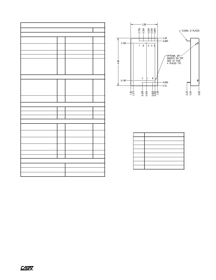
Mechanical tolerances unless otherwise noted:
X.XX dimensions: ±0.020 inches
X.XXX dimensions: ±0.005 inches
Seal around terminals is not hermetic. Do not immerse units in any
liquid.
BOTTOM VIEW
SIDE VIEW
(3)
Determine the correct fuse size by calculating the maximum DC
current drain at low line input, maximum load and then adding 50
to 100 percent to get the desired fuse size. Slow blowing fuse
recommended.
(4)
The Case is tied to the -Input pin through 1.5 Megohm in parallel
with 0.01µF.
(5)
Minimum load required for specified performance only. Module
may be run at less than minimum load with no damage.
Maximum power from module is limited to either 50 or 60 Watts.
Trimming the output up reduces the output current proportionally
to keep the maximum power constant. Output current is not
increased over the listed maximum when trimming the output
voltage down.
(6)
Short term stability is specified after a 30 minute warmup at full
load, constant line and recording the drift over a 24 hour period.
(7)
The transient response is specified as the time required to settle
from a 50 to 75 % step load change (rise time of step = 2 µSec)
to a 50mV error band.
(8)
Dynamic response is the peak overshoot during a transient as
defined in note 6 above.
(9)
The input ripple rejection is specified for DC to 120 Hz ripple with
a modulation amplitude of 1% of Vin.
(10) 1500W peak pulse power transient voltage protectors used, also
see note 3.
(11) The functional temperature range is intended to give an additional
data point for use in evaluating this power supply. At the low
functional temperature the power supply will function with no
side effects, however sustained operation at the high functional
temperature may reduce the expected operational life. The data
sheet specifications are not guaranteed over the functional
temperature range.
(12) The case thermal impedance is specified as the case temperature
rise over ambient per package watt dissipated. The -HS option
can reduce the thermal impedance of the XW single to below 2.4
∞C per Watt. See the applications section.
(13) Full output trim range may not be available at full load and
minimum input voltage. Full trim is guaranteed from minimum
input voltage +5% and full load. Also see note 5.
(14) The remote sense pins must be connected to their respective
outputs for proper output accuracy and regulation. The remote
sense lines can correct for 0.4V maximum drop on each line.
(15) Water Washability - Calex DC/DC converters are designed to
withstand most solder/wash processes. Careful attention should
be used when assessing the applicability in your specific
manufacturing process. Converters are not hermetically sealed.

A
50 to 60 XW Single Series DC/DC Converters
Manufacturing Company, Inc. ∑ Concord, California 94520 ∑ Ph: 925/687-4411 or 800/542-3355 ∑ Fax: 925/687-3333 ∑ www.calex.com ∑ Email: sales@calex.com
4
eco# 041007-1
Application Information
You truly get what you pay for in a CALEX converter; a
complete system oriented and specified DC/DC converter -
no surprises, no external noise filtering circuits needed, no
external transient suppression necessary and no heatsinking
problems.
The 50/60 Watt XW Single series, like all CALEX converters,
carries the full 5 Year CALEX Warranty. We can offer a five
year warranty where others can't because with CALEX it's
rarely needed.
General Information
The 220 kHz operating frequency of the 50/60 Watt XW Single
Series allows an increased power density of up to 6 Watts per
cubic inch while still including adequate heat sinking and full
dual stage filtering on both the input and output. This prevents
the need for additional filtering and heatsinking in most
applications.
The series is also useful for battery operation in industrial,
medical control and remote data collection applications. The
remote ON/OFF pin places the converter in a very low power
mode that draws typically less than 7mA (2mA for 12S
models) from the input source.
Noise has also been greatly reduced in this single design.
The industry standard specifies output noise at 75 mV peak-
to- peak typical with no mention of maximum value or of
measurement bandwidth. Our converters achieve 15 mV
peak-to-peak typical and are fully specified and tested to a
maximum specification of 50 mV peak-to-peak over a wide
bandwidth of 0-20 MHz.
Dual stage input filtering reduces reflected ripple noise and
is also fully specified for typical and maximum values (exact
value depends on input voltage range). Typical RMS noise
over a 10 kHz to 1 MHz bandwidth is also specified for both the
input and output.
All inputs and outputs are protected from transient
overvoltage conditions by 1500 watt transient overvoltage
suppressors. Full overload protection is provided by
independent pulse-by-pulse current limiting and an over-
temperature shutdown circuit. These protection features
assure you that our 50/60 Watt Single will provide you with
zero failure rate operation.
Six sided shielding is standard along with specified operation
over the full industrial temperature range of -40 to +85∞C.
General Operation
Figure 1 shows the recommended connections for the 50 Watt
Single DC/DC converter. A fuse is recommended to protect
the input circuit and should not be omitted. The fuse serves
two purposes:
1) It prevents unlimited current from flowing in the case of a
catastrophic system failure.
2) UL regulations for telecom equipment require the use of a
fuse.
The ON/OFF and TRIM pins may be left floating if they are not
used. No external capacitance on either the input or outputs
Figure 1.
Standard connections for the 50/60 Watt Single Series. The ON/
OFF and TRIM pins can be left floating if they are not used. The input
fuse should not be omitted. The remote sense lines should be
connected to their respective output pins even if they are not used
in your application
is required for normal operation. In fact, it can degrade the
converters performance. See our application note
"Understanding DC/DC Converters Output Impedance" for
more information. The usual 0.1 to 0.01 µF bypasses may be
used around your PCB as required for local bypassing without
harm.
Extremely low ESR capacitors (< 0.5 ohms) should not be
used at the input. This will cause peaking of the input filters
transfer function and actually degrade the filters
performance.
Output
The trim pin may be used to adjust the outputs by up to ±5 %
from the nominal factory setting. The trim may be used to
adjust for system wiring voltage drops or to adjust the +5
output up to 5.2 Volts for ECL applications. Figure 2 shows the
proper connections for using the trim pin. If output trimming is
not desired the trim pin may be safely left floating.
Maximum power is limited to either 50 or 60 watts. Trimming
the output up reduces the output current proportionally to
keep the maximum power constant. Output current is not
increased over the listed maximum when trimming the output
voltage down.
Figure 2.
The 5 Volt output can be trimmed by either a trimpot or fixed
resistors. If fixed resistors are used their values may range from
zero to infinite ohms. The trimpot should be 10 K ohms nominal.
A
50 to 60 XW Single Series DC/DC Converters
Manufacturing Company, Inc. ∑ Concord, California 94520 ∑ Ph: 925/687-4411 or 800/542-3355 ∑ Fax: 925/687-3333 ∑ www.calex.com ∑ Email: sales@calex.com
5
eco# 041007-1
Each single output features provisions for remote sense
connections. These allow the power supply to correct for line
drops of up to 0.4 volts per leg. The remote sense connections
should be made with twisted pair wire or closely coupled PCB
traces. If the remote sense is not to be used, these pins must
be connected to their respective output pins for proper output
voltage accuracy and regulation. There is approximately 1 mA
of current flowing in the remote sense lines.
Care should be taken not to disconnect the output pins
before the remote sense pins while the converter is in operation.
If this happens the output load current will run down the sense
leads, possibly creating an output overvoltage condition that
could cause the internal transient suppressor on the output to
conduct. If the unit must be "Hot Plugged" in the intended
application, provisions should be made to disconnect the
sense leads before the power leads, disconnect the input
power first or use the remote ON/OFF to stop the converter's
operation.
See our application note on remote sense and trim functions
for more information.
Grounding
The input and output sections are fully floating from each
other. They may be operated separately or with a common
ground. If the input and output sections are connected either
directly at the converter or at some remote location from the
converter it is suggested that a 3.3 to 10µF, 0.5 to 5 ohm ESR
capacitor bypass be used directly at the converter output pins.
This capacitor prevents any common mode switching currents
from showing up at the converter's output as normal mode
output noise. Do not use the lowest ESR, biggest value
capacitor that you can find! This can only lead to reduced
system performance or oscillation. See our application note
"Understanding Output Impedance For Optimum Decoupling"
for more information.
Case Grounding
The case serves not only as a heat sink but also as an EMI
shield. The case / header shield is tied to the -Input pin through
a 1.5 megohm resistor in parallel with a 0.01 µF capacitor.
These connections are shown on the block diagram. The case
is floating from the output sections.
The noise performance of the converter may improve or
degrade with the case connected to other inputs or outputs
depending on your system grounding.
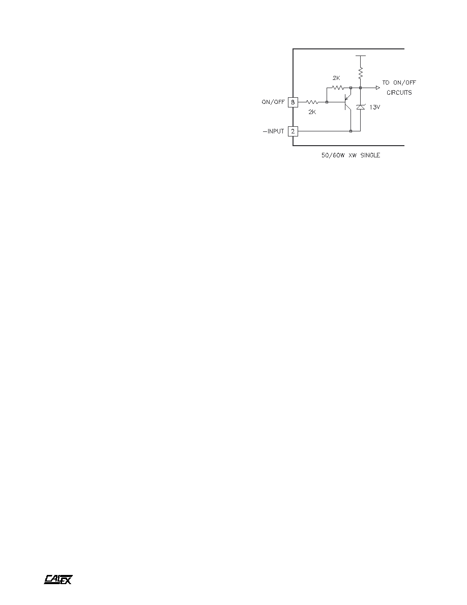
Remote ON/OFF Pin Operation
The remote ON/OFF pin may be left floating if this function is
not used. The equivalent input circuit for the ON/OFF pin is
shown in figure 3. The best way to drive this pin is with an open
collector/drain or relay contact. See our application note titled
"Understanding the Remote ON/OFF Function" for more
information on using the remote ON/OFF pin.
When the ON/OFF pin is pulled low with respect to the -
Input, the converter is placed in a low power drain state. When
Figure 3.
The simplified schematic of the XW Single Series' ON/OFF pin. The
maximum open circuit voltage is clamped by the 13 volt zener. By
leaving this pin floating the converter will be in the ON state. When
the pin is pulled below 5 volts the converter is placed in the power
down or OFF state. See our application note on the remote ON/OFF
function for more information.
the ON/OFF pin is released the converter completely powers
up in typically 60 milliseconds. The ON/OFF pin turns the
converter off while keeping the input bulk capacitor fully
charged. This prevents the large inrush current spike that
occurs when the +input pin is opened and closed.
Temperature Derating/Mounting Options
The XW Single series can operate up to 85∞C case temperature
without derating. Case temperature may be roughly calculated
from ambient by knowing that the XW Singles case temperature
rise is approximately 3.4∞ C per package watt dissipated.
For example: If the converter was outputting 40 watts, at what
ambient could it expect to run with no moving air and no extra
heatsinking?
Efficiency is approximately 85%. This leads to an input
power of 47 watts. The case temperature rise would be 7 watts
x 3.4 = 24∞C. This number is subtracted from the maximum
case temperature of 85∞C to get: 61∞C.
This is a rough approximation of the maximum ambient
temperature. Because of the difficulty of defining ambient
temperature and the possibility that the load's dissipation may
actually increase the local ambient temperature significantly,
these calculations should be verified by actual measurement
before committing to a production design.
Heat Sink Option
The XW Single can be ordered in a "-I" configuration which
provides a case with 4 X M3 inserts located on the top surface
of the case for attaching a heat sink or mounting the converter
on its back. The mounting surface should be flat to within
±0.01 inches to prevent warping the XW Single's case.
The CALEX -HS heat sink was specially developed for this
model and can reduce the case temperature rise to below
2.4∞C per watt with natural convection and even less with
moving air. It also increases the heat removing efficiency of
any cooling air flow.