 | –≠–ª–µ–∫—Ç—Ä–æ–Ω–Ω—ã–π –∫–æ–º–ø–æ–Ω–µ–Ω—Ç: 24T3.12HE | –°–∫–∞—á–∞—Ç—å:  PDF PDF  ZIP ZIP |
A
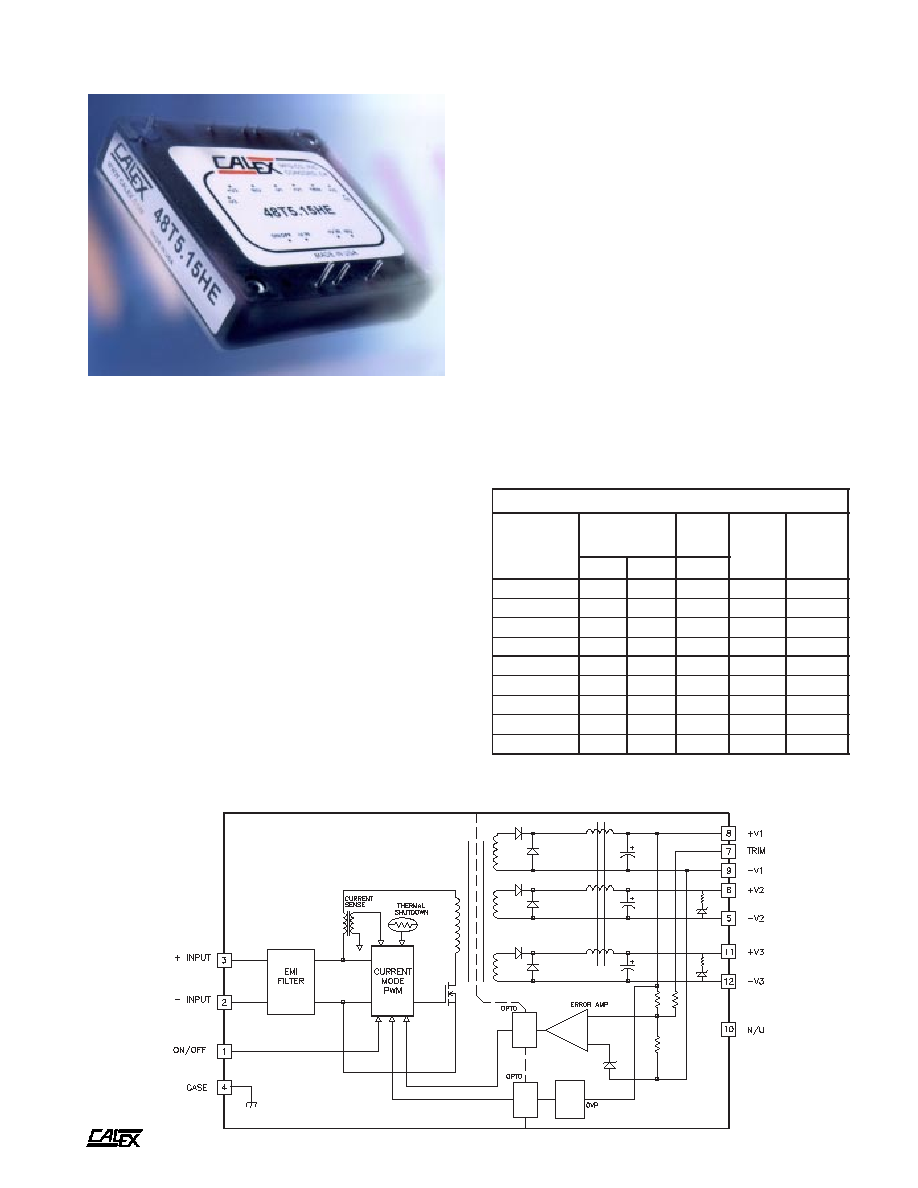
75 Watt HE Triple Series DC/DC Converters
2401 Stanwell Drive ∑ Concord, California 94520 ∑ Ph: 925/687-4411 or 800/542-3355 ∑ Fax: 925/687-3333 ∑ www.calex.com ∑ Email: sales@calex.com
1
1/6/2004, eco#: 041007-1, 050210-3, 050503-1, 050713-2 , 050906-1 051014-5
Features
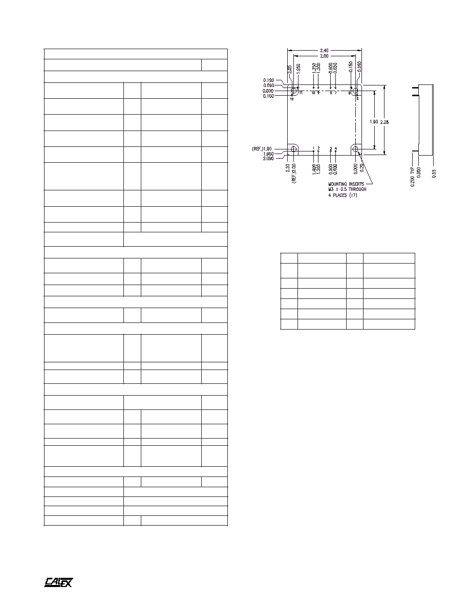
Small size, 2.4"x2.28"x0.53" half-brick package
Excellent thermal performance with metal baseplate
High Efficiency
Volt-seconds clamp and fast over voltage protection
Pulse-by-pulse current limiting, short circuit
frequency foldback
Over-temperature protection
Auto-softstart
Low noise
Constant frequency for normal operation.
2:1 input voltage range
Positive logic primary remote ON/OFF
Negative logic primary shutdown as an option
Very low temperature coefficient
Water Washable
Trimmable output voltage
Low cost
5 Year Warranty
Description
The Standard Triple HE DC/DC converter provides three
regulated low voltage DC outputs at high efficiency and low
cost. The unit has feedback from the +5Vdc or +23Vdc output.
The auxilliary outputs are cross regulated to the main feedback
loop (reference the block diagram). The Standard Triple HE
meets rigorous requirements in an industry standard case
size and is well suited for most telecommunication applications.
The Standard Triple HE includes primary remote on/off control
plus threaded-through holes to allow easy mounting or the
addition of a heat sink for high temperature use.
The output currents are the maximum ratings of each of the outputs. It is up to
the user to ensure that the total power output is below 75 Watts.
t
r
a
h
C
n
o
i
t
c
e
l
e
S
l
e
d
o
M
e
g
n
a
R
t
u
p
n
I
C
D
V
n
i
I
@
C
D
A
m
o
n
t
u
o
V
C
D
V
t
u
o
I
C
D
A
n
i
M
x
a
M
p
y
T
E
H
2
1
.
3
T
4
2
8
1
6
3
1
8
.
3
2
1
±
,
3
.
3
0
.
2
±
,
0
2
E
H
5
1
.
3
T
4
2
8
1
6
3
6
7
.
3
5
1
±
,
3
.
3
0
.
2
±
,
0
2
E
H
2
1
.
5
T
4
2
8
1
6
3
3
6
.
3
2
1
±
,
5
0
.
2
±
,
5
1
E
H
5
1
.
5
T
4
2
8
1
6
3
0
6
.
3
5
1
±
,
5
0
.
2
±
,
5
1
E
H
2
1
.
3
T
8
4
6
3
5
7
8
8
.
1
2
1
±
,
3
.
3
0
.
2
±
,
0
2
E
H
5
1
.
3
T
8
4
6
3
5
7
6
8
.
1
5
1
±
,
3
.
3
0
.
2
±
,
0
2
E
H
2
1
.
5
T
8
4
6
3
5
7
0
8
.
1
2
1
±
,
5
0
.
2
±
,
5
1
E
H
5
1
.
5
T
8
4
6
3
5
7
9
7
.
1
5
1
±
,
5
0
.
2
±
,
5
1
E
H
7
1
.
5
T
8
4
6
3
5
7
8
7
.
1
7
1
±
,
5
0
.
2
±
,
5
1
74 Watt HE Triple Series Blcok Diagram

A
75 Watt HE Triple Series DC/DC Converters
2401 Stanwell Drive ∑ Concord, California 94520 ∑ Ph: 925/687-4411 or 800/542-3355 ∑ Fax: 925/687-3333 ∑ www.calex.com ∑ Email: sales@calex.com
2
1/6/2004, eco#: 041007-1, 050210-3, 050503-1, 050713-2 , 050906-1 051014-5
Unless otherwise stated, these specifications apply for ambient temperature T
A
=23 ±2∞C, nominal input voltage, and rated full load. (1)
s
r
e
t
e
m
a
r
a
P
t
u
p
n
I
l
e
d
o
M
E
H
2
1
.
3
T
4
2
E
H
5
1
.
3
T
4
2
E
H
2
1
.
5
T
4
2
E
H
5
1
.
5
T
4
2
s
t
i
n
U
e
g
n
a
R
e
g
a
t
l
o
V
N
I
M
P
Y
T
X
A
M
8
1
4
2
6
3
C
D
V
e
g
a
t
l
o
v
r
e
v
O
t
u
p
n
I
c
e
S
m
0
0
1
X
A
M
0
5
C
D
V
n
o
i
t
c
e
j
e
R
e
l
p
p
i
R
t
u
p
n
I
)
z
H
0
2
1
(
P
Y
T
0
5
B
d
t
u
o
k
c
o
L
e
g
a
t
l
o
v
r
e
d
n
U
s
e
Y
n
o
i
t
c
e
t
o
r
P
e
g
a
t
l
o
V
e
s
r
e
v
e
R
t
u
p
n
I
s
e
Y
d
a
o
L
o
N
t
n
e
r
r
u
C
t
u
p
n
I
d
a
o
L
%
0
0
1
P
Y
T
P
Y
T
2
1
6
.
3
A
m
A
t
n
e
r
r
u
C
h
s
u
r
n
I
X
A
M
5
.
0
A
2
S
H
µ
2
1
,
e
l
p
p
i
R
d
e
t
c
e
l
f
e
R
)
3
(
e
c
n
a
d
e
p
m
I
e
c
r
u
o
S
P
Y
T
0
2
P
-
P
A
m
y
c
n
e
i
c
i
f
f
E
P
Y
T
2
8
3
8
6
8
7
8
%
y
c
n
e
u
q
e
r
F
g
n
i
h
c
t
i
w
S
P
Y
T
5
2
3
z
H
k
e
s
u
F
d
e
d
n
e
m
m
o
c
e
R
)
2
(
S
P
M
A
s
r
e
t
e
m
a
r
a
P
t
u
p
n
I
l
e
d
o
M
E
H
2
1
.
3
T
8
4
E
H
5
1
.
3
T
8
4
E
H
2
1
.
5
T
8
4
E
H
5
1
.
5
T
8
4
E
H
7
1
.
5
T
8
4
s
t
i
n
U
e
g
n
a
R
e
g
a
t
l
o
V
N
I
M
P
Y
T
X
A
M
6
3
8
4
5
7
C
D
V
e
g
a
t
l
o
v
r
e
v
O
t
u
p
n
I
c
e
S
m
0
0
1
X
A
M
5
8
C
D
V
n
o
i
t
c
e
j
e
R
e
l
p
p
i
R
t
u
p
n
I
)
z
H
0
2
1
(
P
Y
T
0
5
B
d
t
u
o
k
c
o
L
e
g
a
t
l
o
v
r
e
d
n
U
s
e
Y
n
o
i
t
c
e
t
o
r
P
e
g
a
t
l
o
V
e
s
r
e
v
e
R
t
u
p
n
I
s
e
Y
t
n
e
r
r
u
C
t
u
p
n
I
d
a
o
L
o
N
d
a
o
L
%
0
0
1
P
Y
T
P
Y
T
2
1
8
.
1
A
m
A
t
n
e
r
r
u
C
h
s
u
r
n
I
X
A
M
5
.
0
A
2
S
H
µ
2
1
,
e
l
p
p
i
R
d
e
t
c
e
l
f
e
R
)
3
(
e
c
n
a
d
e
p
m
I
e
c
r
u
o
S
P
Y
T
0
2
P
-
P
A
m
y
c
n
e
i
c
i
f
f
E
P
Y
T
3
8
4
8
7
8
8
8
8
8
%
y
c
n
e
u
q
e
r
F
g
n
i
h
c
t
i
w
S
P
Y
T
5
2
3
z
H
k
e
s
u
F
d
e
d
n
e
m
m
o
c
e
R
)
2
(
S
P
M
A
NOTES:
(1)
Refer to the CALEX Application Notes for the definition of terms,
measurement circuits, and other information.
(2)
These units are not fused and need to be fused by the user.
Refer to the CALEX Application Notes for information on fusing.
For inrush current, refer to the specifications above.
(3)
33 µF capacitor connected to two "Input" pins. Then place
current sensor in series with 12 µH inductor between 33 µF and
the source. The reflected ripple current is measured over 5 Hz
to 20 MHz bandwidth. Noise should be minimized in the
measurement.
(4)
Noise is measured per the CALEX Application Notes. Output
noise is measured with a 10 µF tantalum capacitor in parallel
with a 0.1 µF ceramic capacitor connected across the output to
CMN. Measurement bandwidth is 0-20 MHz.
(5)
Optimum performance is obtained when this power supply is
operated within the minimum to maximum load specifications.
No damage to module will occur, when the output is operated at
less than minimum load, but the output voltage may contain a
low frequency component that may exceed output noise
specifications. Total output power should not exceed 75W.
(6)
Load Transient Recovery Time is defined as the time for the
output to settle from a 50 to 75% or 25% step load change to a
1% error band of output voltage(rise time of step = 2µ Sec).
(7)
Load Transient Overshoot is defined as the peak overshoot
during a transient as defined in the Note 6 above.
(8)
Load regulation is defined as the output voltage change when
changing load current from maximum to minimum. The voltage
is measured at the output pin.
(9)
Cross regulation is defined as the change in one output (set at
70% of maximum load) when only one of the other outputs is
changed from 70% of maximum to 20% of maximum load.
(10) Most switches would be suitable for logic On/Off control, in case
there is a problem, you can make following estimation and then
leave some margin.
When open collector is used for logic high, "Open Circuit Voltage
at On/Off Pin", "Output Resistance" and "External Leakage
Current Allowed for Logic High" are used to estimate the high
impedance requirement of open collector.
When switch is used for logic low, "Open Circuit Voltage at On/
Off Pin", "Output Resistance" and "LOW Logic Level" are used
to estimate the low impedance requirement of switch.

A
75 Watt HE Triple Series DC/DC Converters
2401 Stanwell Drive ∑ Concord, California 94520 ∑ Ph: 925/687-4411 or 800/542-3355 ∑ Fax: 925/687-3333 ∑ www.calex.com ∑ Email: sales@calex.com
3
1/6/2004, eco#: 041007-1, 050210-3, 050503-1, 050713-2 , 050906-1 051014-5
Unless otherwise stated, these specifications apply for ambient temperature T
A
=23 ±2∞C, nominal input voltage, and rated full load. (1)
s
r
e
t
e
m
a
r
a
P
t
u
p
t
u
O
)
1
O
V
(
l
e
d
o
M
E
H
2
1
.
3
T
4
2
E
H
5
1
.
3
T
4
2
E
H
2
1
.
3
T
8
4
E
H
5
1
.
3
T
8
4
E
H
2
1
.
5
T
4
2
E
H
5
1
.
5
T
4
2
E
H
2
1
.
5
T
8
4
E
H
5
1
.
5
T
8
4
E
H
7
1
.
5
T
8
4
s
t
i
n
U
e
g
a
t
l
o
V
t
u
p
t
u
O
3
.
3
5
C
D
V
e
g
a
t
l
o
V
t
u
p
t
u
O
y
c
a
r
u
c
c
A
t
n
i
o
p
t
e
S
X
A
M
1
±
%
t
o
o
h
s
r
e
v
O
n
O
n
r
u
T
P
Y
T
0
%
t
n
e
i
c
i
f
f
e
o
C
e
r
u
t
a
r
e
p
m
e
T
P
Y
T
X
A
M
3
0
0
.
0
1
0
.
0
C
∞
/
%
e
l
p
p
i
R
&
e
s
i
o
N
)
4
(
S
M
R
P
Y
T
P
Y
T
6
6
3
3
0
0
1
0
5
P
-
P
V
m
)
2
1
(
)
5
(
t
n
e
r
r
u
C
d
a
o
L
N
I
M
X
A
M
2
0
2
5
.
1
5
1
A
)
7
(
t
o
o
h
s
r
e
v
O
t
n
e
i
s
n
a
r
T
d
a
o
L
P
Y
T
4
%
)
6
(
e
m
i
T
y
r
e
v
o
c
e
R
t
n
e
i
s
n
a
r
T
d
a
o
L
P
Y
T
0
0
2
c
e
S
µ
)
8
(
n
o
i
t
a
l
u
g
e
R
d
a
o
L
d
a
o
L
x
a
M
-
n
i
M
P
Y
T
X
A
M
5
0
.
0
4
.
0
%
n
o
i
t
a
l
u
g
e
R
e
n
i
L
x
a
M
-
n
i
M
=
n
i
V
P
Y
T
X
A
M
1
0
.
0
1
.
0
%
)
P
V
O
(
n
o
i
t
c
e
t
o
r
P
e
g
a
t
l
o
v
r
e
v
O
d
l
o
h
h
s
e
r
h
T
g
n
i
h
c
t
a
l
-
n
o
N
-
e
p
y
T
P
V
O
p
m
a
l
C
e
g
a
t
l
o
v
r
e
v
O
p
o
o
L
n
e
p
O
P
Y
T
0
3
1
%
t
i
m
i
L
t
n
e
r
r
u
C
t
u
p
t
u
O
m
o
n
-
t
u
o
V
f
o
%
0
9
=
t
u
o
V
P
Y
T
0
2
1
%
t
n
e
r
r
u
C
t
i
u
c
r
i
C
t
r
o
h
S
t
u
p
t
u
O
V
5
2
.
0
=
t
u
o
V
X
A
M
5
7
1
%
s
r
e
t
e
m
a
r
a
P
t
u
p
t
u
O
)
3
O
V
,
2
O
V
(
l
e
d
o
M
E
H
2
1
.
3
T
4
2
E
H
2
1
.
5
T
4
2
E
H
2
1
.
3
T
8
4
E
H
2
1
.
5
T
8
4
E
H
5
1
.
3
T
4
2
E
H
5
1
.
5
T
4
2
E
H
5
1
.
3
T
8
4
E
H
5
1
.
5
T
8
4
E
H
7
1
.
5
T
8
4
s
t
i
n
U
e
g
a
t
l
o
V
t
u
p
t
u
O
2
1
±
5
1
±
7
1
±
C
D
V
e
g
a
t
l
o
V
t
u
p
t
u
O
y
c
a
r
u
c
c
A
t
n
i
o
p
t
e
S
X
A
M
5
.
2
±
%
t
o
o
h
s
r
e
v
O
n
O
n
r
u
T
P
Y
T
0
%
t
n
e
i
c
i
f
f
e
o
C
e
r
u
t
a
r
e
p
m
e
T
P
Y
T
X
A
M
2
0
.
0
5
0
.
0
C
∞
/
%
e
l
p
p
i
R
&
e
s
i
o
N
)
4
(
S
M
R
P
Y
T
P
Y
T
0
5
1
0
0
1
0
5
1
0
0
1
0
0
2
0
5
1
0
0
2
0
5
1
0
0
2
0
5
1
P
-
P
V
m
)
2
1
(
)
5
(
t
n
e
r
r
u
C
d
a
o
L
N
I
M
X
A
M
2
.
0
2
A
)
7
(
t
o
o
h
s
r
e
v
O
t
n
e
i
s
n
a
r
T
d
a
o
L
P
Y
T
4
%
)
8
(
n
o
i
t
a
l
u
g
e
R
d
a
o
L
d
a
o
L
x
a
M
-
n
i
M
P
Y
T
X
A
M
2
4
%
n
o
i
t
a
l
u
g
e
R
e
n
i
L
x
a
M
-
n
i
M
=
n
i
V
P
Y
T
X
A
M
5
.
0
1
%
)
9
(
n
o
i
t
a
l
u
g
e
R
s
s
o
r
C
P
Y
T
4
%
n
o
i
t
a
l
u
g
e
R
e
t
u
l
o
s
b
A
P
Y
T
8
%
n
o
i
t
c
e
t
o
r
P
e
g
a
t
l
o
V
t
u
p
t
u
O
p
m
a
l
C
e
g
a
t
l
o
v
r
e
v
O
p
o
o
L
n
e
p
O
)
p
m
a
l
C
s
d
n
o
c
e
S
-
t
l
o
V
(
s
e
Y
(11) Thermal impedance is tested with the converter mounted vertically
and facing another printed circuit board 1/2 inch away. If
converter is mounted horizontally with no obstructions, thermal
impedance is approximately 7 ∞C/W.
(12) Minimum load is defined as 10% of maximum load. Calex Mfg.
Co. Inc. does not guarantee performance for loads less than the
minimum. Loads less than the minimum shall not damage the
unit.
(13) The unit can be configured with negative logic for Remote ON/
OFF.
(14) When an external On/Off switch is used, such as open collector
switch, logic high requires the switch to be high-impedance.
Switch leakage currents greater than 10 uA may be sufficient to
trigger the ON/Off to the logic-low state.
(15) When using the trim function, the user should remember that all
three voltages will go up or down at the same time.
(16) Water Washability - Calex DC/DC converters are designed to
withstand most solder/wash processes. Careful attention should
be used when assessing the applicability in your specific
manufacturing process. Converters are not hermetically sealed.
(17) Torque fasteners into threaded mounting inserts at 12 in. oz. or
less. Greater torque may result in damage to unit and void the
warranty.
A
75 Watt HE Triple Series DC/DC Converters
2401 Stanwell Drive ∑ Concord, California 94520 ∑ Ph: 925/687-4411 or 800/542-3355 ∑ Fax: 925/687-3333 ∑ www.calex.com ∑ Email: sales@calex.com
4
1/6/2004, eco#: 041007-1, 050210-3, 050503-1, 050713-2 , 050906-1 051014-5
n
i
P
n
o
i
t
c
n
u
F
n
i
P
n
o
i
t
c
n
u
F
1
y
r
a
m
i
r
P
F
F
O
/
N
O
7
M
I
R
T
2
N
I
V
-
8
1
V
+
3
N
I
V
+
9
1
V
-
4
e
s
a
C
0
1
U
/
N
5
2
V
-
1
1
3
V
+
6
2
V
+
2
1
3
V
-
s
n
o
i
t
a
c
i
f
i
c
e
p
S
l
a
r
e
n
e
G
s
l
e
d
o
M
l
l
A
s
t
i
n
U
n
o
i
t
c
n
u
F
F
F
O
/
N
O
e
t
o
m
e
R
y
r
a
m
i
r
P
l
e
v
e
L
c
i
g
o
L
H
G
I
H
N
O
r
o
f
X
A
M
0
.
3
C
D
V
t
n
e
r
r
u
C
e
g
a
k
a
e
L
l
a
n
r
e
t
x
E
)
4
1
(
h
g
i
H
c
i
g
o
L
r
o
f
d
e
w
o
ll
A
X
A
M
0
1
A
µ
n
o
i
t
c
e
t
o
r
P
e
d
o
i
D
t
u
p
n
I
e
g
a
t
l
o
V
X
A
M
0
5
C
D
V
l
e
v
e
L
c
i
g
o
L
W
O
L
t
u
p
n
I
-
o
t
n
i
P
F
F
O
/
N
O
e
i
T
r
o
P
Y
T
0
.
1
C
D
V
y
r
a
m
i
r
P
r
o
f
t
n
e
r
r
u
C
g
n
i
k
n
i
S
l
e
v
e
L
c
i
g
o
L
X
A
M
0
0
5
A
µ
t
a
e
g
a
t
l
o
V
t
i
u
c
r
i
C
n
e
p
O
)
0
1
(
n
i
P
f
f
O
/
n
O
y
r
a
m
i
r
P
c
i
g
o
L
e
v
i
t
i
s
o
P
c
i
g
o
L
e
v
i
t
a
g
e
N
P
Y
T
P
Y
T
3
.
2
5
.
1
C
D
V
C
D
V
)
0
1
(
e
c
n
a
t
s
i
s
e
R
t
u
p
t
u
O
P
Y
T
3
m
h
O
k
t
n
e
r
r
u
C
e
l
d
I
)
F
F
O
s
i
e
l
u
d
o
M
(
P
Y
T
2
C
D
A
m
r
o
r
r
e
%
1
o
t
e
m
i
T
n
o
-
n
r
u
T
P
Y
T
0
2
c
e
S
m
)
3
1
(
c
i
g
o
L
F
F
O
/
N
O
e
t
o
m
e
R
N
O
e
l
u
d
o
M
-
H
G
I
H
F
F
O
e
l
u
d
o
M
-
W
O
L
m
i
r
T
e
g
a
t
l
o
V
t
u
p
t
u
O
e
g
n
a
R
m
i
r
T
N
I
M
X
A
M
0
1
±
f
o
%
t
u
o
V
e
c
n
a
t
s
i
s
e
R
t
u
p
n
I
P
Y
T
0
1
m
h
O
k
e
g
a
t
l
o
V
t
i
u
c
r
i
C
n
e
p
O
P
Y
T
5
.
2
V
t
i
m
i
L
m
i
r
T
e
g
a
t
l
o
V
t
u
p
t
u
O
m
u
m
i
x
a
M
X
A
M
0
1
1
f
o
%
t
u
o
V
n
o
i
t
a
l
o
s
I
n
o
i
t
a
l
o
s
I
t
u
p
t
u
O
o
t
t
u
p
n
I
e
g
a
k
a
e
L
A
µ
0
1
V
4
2
=
m
o
n
V
V
8
4
=
m
o
n
V
X
A
M
X
A
M
0
0
7
4
4
5
1
C
D
V
C
D
V
e
c
n
a
t
s
i
s
e
R
t
u
p
t
u
O
o
t
t
u
p
n
I
N
I
M
0
1
m
h
o
M
t
u
p
t
u
O
o
t
t
u
p
n
I
e
c
n
a
t
i
c
a
p
a
C
P
Y
T
0
0
8
1
F
P
l
a
t
n
e
m
n
o
r
i
v
n
E
e
r
o
c
ll
e
B
,
F
B
T
M
d
e
t
a
l
u
c
l
a
C
1
e
s
a
C
,
1
d
o
h
t
e
M
0
0
0
,
0
0
0
,
1
>
r
H
g
n
i
t
a
r
e
p
O
e
t
a
l
p
e
s
a
B
e
g
n
a
R
e
r
u
t
a
r
e
p
m
e
T
N
I
M
X
A
M
0
4
-
0
0
1
C
∞
e
r
u
t
a
r
e
p
m
e
T
e
g
a
r
o
t
S
N
I
M
X
A
M
0
4
-
0
2
1
C
∞
)
1
1
(
e
c
n
a
d
e
p
m
I
l
a
m
r
e
h
T
P
Y
T
7
W
/
C
∞
n
w
o
d
t
u
h
S
l
a
m
r
e
h
T
e
r
u
t
a
r
e
p
m
e
T
e
t
a
l
p
e
s
a
B
)
t
r
a
t
s
e
R
o
t
u
A
(
P
Y
T
0
1
1
C
∞
l
a
r
e
n
e
G
t
h
g
i
e
W
t
i
n
U
P
Y
T
4
1
1
/
4
g
/
z
o
t
i
K
g
n
i
t
n
u
o
M
s
i
s
s
a
h
C
5
2
S
M
n
o
i
s
n
e
m
i
D
e
s
a
C
"
3
5
.
0
x
"
8
2
.
2
x
"
4
.
2
s
l
a
v
o
r
p
p
A
y
c
n
e
g
A
g
n
i
d
n
e
p
0
5
9
0
6
L
U
s
t
r
e
s
n
I
g
n
i
t
n
u
o
M
n
o
e
u
q
r
o
T
X
A
M
.
z
o
.
n
i
2
1
Mechanical tolerances unless otherwise noted:
X.XX dimensions: ±0.020 inches
X.XXX dimensions: ±0.005 inches