 | –≠–ª–µ–∫—Ç—Ä–æ–Ω–Ω—ã–π –∫–æ–º–ø–æ–Ω–µ–Ω—Ç: 460-100 | –°–∫–∞—á–∞—Ç—å:  PDF PDF  ZIP ZIP |
A
2401 Stanwell Drive ∑ Concord, California 94520 ∑ Ph: 925/687-4411 or 800/542-3355 ∑ Fax: 925/687-3333 ∑ www.calex.com ∑ Email: sales@calex.com
1
4/2001
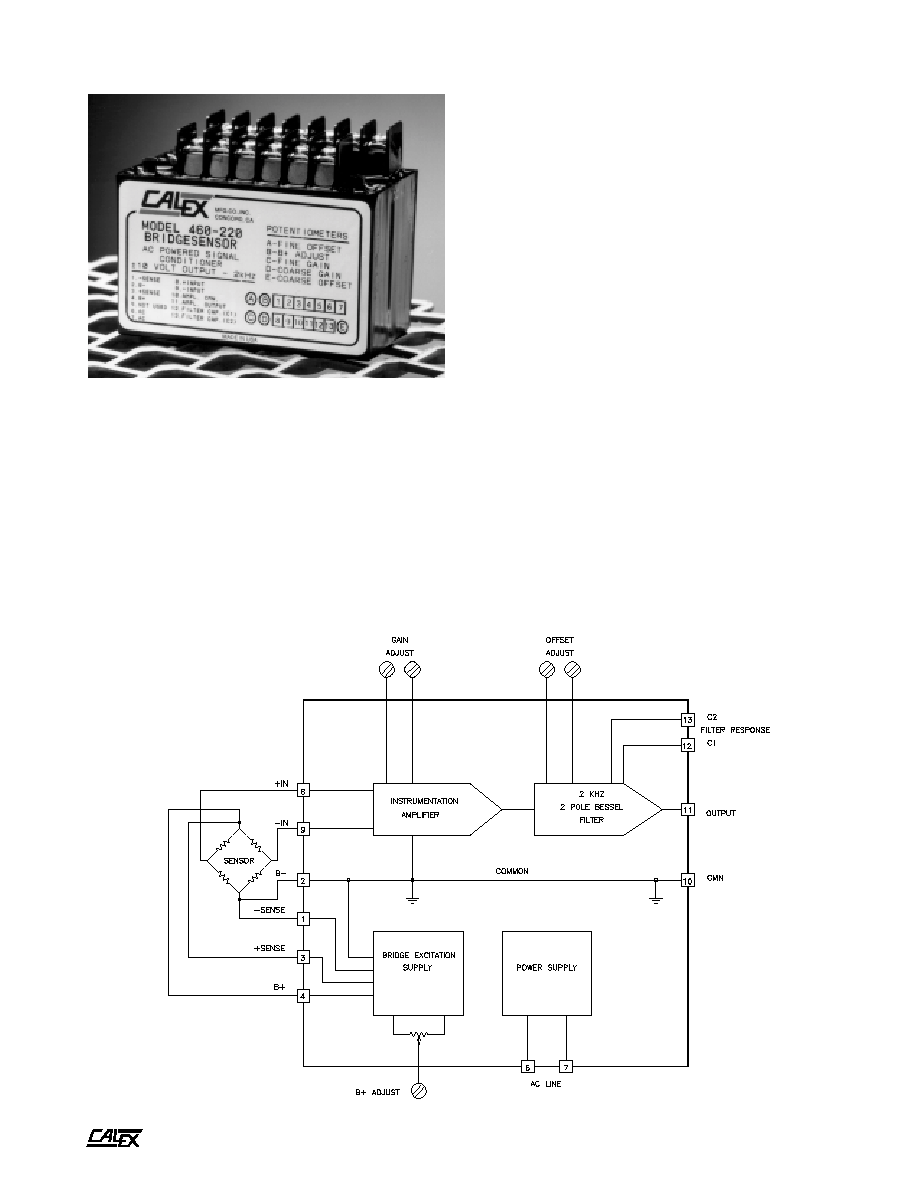
Model 460 Bridgesensor
460 Simplified Block Diagram
Features
!
2 kHz Frequency Response
!
Rugged, Compact And Fully Encapsulated
!
Complete System-just Add AC Power
!
Ready To Use With Screwdriver Wiring
!
Stable and Accurate
Applications
!
Weighing With Load Cells
!
Long Term Structural Monitoring
!
Process Control Pressure Transducers
!
Strain Measurements
Description
The Model 460 Bridgesensor is a self contained, AC powered,
signal conditioning module for bridge type instrumentation. It
contains a precision differential instrumentation amplifier with
filtered output and a highly regulated, low noise, adjustable
output bridge excitation source. The unit is completely
encapsulated for use in rugged environments. The output
filter cutoff frequency is 2000Hz and may be lowered by
adding two external capacitors.

A
2401 Stanwell Drive ∑ Concord, California 94520 ∑ Ph: 925/687-4411 or 800/542-3355 ∑ Fax: 925/687-3333 ∑ www.calex.com ∑ Email: sales@calex.com
2
4/2001
Model 460 Bridgesensor
Specifications
(Typical @ 25∞C unless noted)
Getting Started with the Model 460
I.
Hook Up Procedure
A. Connect the + out of your load cell to the + INPUT,
pin 8.
B. Connect the - out of your load cell to the - INPUT,
pin 9.
Note:
If the ± SENSE are not used in your load cell application,
the connections in step C & D need to be followed. If
the ± SENSE are going to be used, do not jumper
them as described in steps C & D.
C. Connect B +, pin 4, to the + excitation of your load cell
and jumper the + SENSE, pin 3, to B +, pin 4.
D. Connect B -, pin 2, to the - excitation of your load cell
and jumper the - SENSE, pin 1, to B -, pin 2.
E. Connect the VAC power supply to the AC input lines,
pins 6 and 7.
II.
Turn On Procedure
A. Verify that the hook up procedure is complete.
B. Verify the correct AC voltage is applied to the 460; i.e.
100, 115, 220, 230.
C. Turn on the AC source supply to the 460.
D. Set the required EXCITATION supply voltage to the
load cell by adjusting B + ADJUST.
III. Calibration Procedure for Zero Voltage
Adjustment
A. Jumper the + and - input terminals, pins 8 and 9,
together.
B. Connect a volt meter across the output, pins 11 and
10.
C. Adjust the COARSE OFFSET and the FINE OFFSET
potentiometers for the desired ZERO voltage.
IV. Full Scale Voltage Adjustment
A. Remove the jumper between the + and - input terminals
and apply a known load to your load cell, in most
cases it would be 100% of full scale.
B. Adjust the COARSE GAIN and FINE GAIN
potentiometers for the desired FULL SCALE output.
C. Calibration is now complete. However, the user should
recheck the ZERO & FULL SCALE voltage output
before continuing.
r
e
i
f
i
l
p
m
A
e
g
n
a
R
n
i
a
G
0
5
2
-
0
4
t
n
e
i
c
i
f
f
e
o
C
e
r
u
t
a
r
e
p
m
e
T
n
i
a
G
/
m
p
p
0
0
2
∞C
s
i
s
e
r
e
t
s
y
H
r
e
t
e
m
o
i
t
n
e
t
o
P
n
i
a
G
.
x
a
m
n
a
p
s
f
o
%
2
.
0
)
I
T
R
(
t
f
i
r
D
/
V
µ
3
∞C
t
n
e
r
r
u
C
s
a
i
B
t
u
p
n
I
±
A
n
0
3
e
c
n
a
d
e
p
m
I
t
u
p
n
I
l
a
i
t
n
e
r
e
f
f
i
D
e
d
o
M
n
o
m
m
o
C
s
m
h
o
g
e
m
0
0
0
,
3
s
m
h
o
g
e
m
6
)
O
T
R
(
e
s
i
o
N
t
u
p
t
u
O
0
0
1
=
n
i
a
g
t
a
z
H
k
2
o
t
z
H
1
P
-
P
V
m
2
e
s
i
o
N
t
u
p
n
I
s
e
i
c
n
e
u
q
e
r
F
e
n
i
L
P
-
P
V
µ
5
1
e
r
a
T
-
t
e
s
f
f
O
t
u
p
t
u
O
e
g
n
a
R
t
f
i
r
D
V
2
+
o
t
V
5
-
±
/
V
m
2
.
0
∞C
n
o
i
t
c
e
j
e
R
e
d
o
M
n
o
m
m
o
C
)
z
H
0
6
-
C
D
(
0
4
=
n
i
a
G
)
z
H
0
6
-
C
D
(
0
5
2
=
n
i
a
G
B
d
0
9
B
d
0
0
1
)
d
a
o
l
k
2
(
t
u
p
t
u
O
d
e
t
a
R
±
V
0
1
e
c
n
a
d
e
p
m
I
t
u
p
t
u
O
z
H
k
2
o
t
C
D
m
h
o
1
o
t
s
m
h
o
1
0
.
0
e
s
n
o
p
s
e
R
c
i
m
a
n
y
D
e
l
o
p
o
w
t
B
d
3
-
o
t
C
D
r
e
t
l
i
F
l
e
s
s
e
B
z
H
k
2
e
g
a
t
l
o
V
t
u
p
n
I
e
d
o
M
n
o
m
m
o
C
6
±
V
5
.
y
l
p
p
u
S
e
g
d
i
r
B
t
u
p
n
I
C
A
V
5
1
1
±
z
H
0
6
o
t
0
5
%
0
1
C
A
V
0
3
2
&
0
2
2
,
0
0
1
(
)
e
l
b
a
l
i
a
v
a
e
g
a
t
l
o
V
t
u
p
t
u
O
s
t
l
o
V
5
1
o
t
4
t
n
e
r
r
u
C
t
u
p
t
u
O
A
m
0
2
1
)
e
v
r
u
c
t
n
e
r
r
u
c
s
v
e
g
a
t
l
o
v
t
u
p
t
u
o
e
e
s
(
%
5
0
.
0
n
o
i
t
a
l
u
g
e
R
e
n
i
L
&
d
a
o
L
A
m
0
0
1
o
t
0
=
L
I
,
V
2
1
=
T
U
O
V
e
s
i
o
N
t
u
p
t
u
O
S
M
R
V
m
5
.
0
t
f
i
r
D
/
m
p
p
0
0
2
∞
.
x
a
m
C
s
i
s
e
r
e
t
s
y
H
r
e
t
e
m
o
i
t
n
e
t
o
P
+
B
.
x
a
m
t
u
p
t
u
o
f
o
%
3
.
0
t
n
e
r
r
u
C
t
i
u
c
r
i
C
t
r
o
h
S
A
m
0
5
7
n
o
i
t
a
l
o
s
I
e
n
i
L
C
D
V
0
0
5
,
1
l
a
c
i
n
a
h
c
e
M
e
r
u
t
a
r
e
p
m
e
T
g
n
i
t
a
r
e
p
O
0∞
0
7
o
t
C
∞C
e
r
u
t
a
r
e
p
m
e
T
e
g
a
r
o
t
S
5
2
-
∞
5
8
+
o
t
C
∞C
t
h
g
i
e
W
)
s
m
a
r
g
0
1
5
(
.
z
o
8
1
e
z
i
S
H
"
7
8
.
2
x
W
"
0
.
2
x
L
"
5
7
.
3
)
m
c
(
2
6
.
7
x
1
.
5
x
3
5
.
9
A
2401 Stanwell Drive ∑ Concord, California 94520 ∑ Ph: 925/687-4411 or 800/542-3355 ∑ Fax: 925/687-3333 ∑ www.calex.com ∑ Email: sales@calex.com
3
4/2001
Model 460 Bridgesensor
0
10
20
30
40
50
60
70
80
90
100
110
120
130
LOAD CURRENT - mA
2
4
6
8
10
12
14
16
B+ VOLTAGE
B+ VOLTAGE vs LOAD CURRENT
460 BRIDGE SUPPLY
SAFE OPERATING AREA
FIGURE 2. Safe Operating Curve
Transducer Excitation
Transducer bridge excitation is provided by an AC line powered,
adjustable, well regulated, low noise power supply. The
excitation voltage is adjustable by means of a molded-in
potentiometer which allows the output voltage to be varied
from 4 to 15 Volts. The output ripple is extremely low and the
line and load regulation are 0.05%.
The sense lines minimize variations in output voltage with
changes in load current or lead resistance. It should be noted
that if the sense feature is not being used, terminal 1 must be
connected to terminal 2. Terminals 3 and 4 must be connected
also. The supply will provide up to 120 mA of output current.
These features make the unit ideal for most common strain
gage bridge circuits of 120, 350, and 500 Ohms.
The supply has short circuit protection to protect it against
short term faults. The output recovers automatically from
short circuit conditions once the short is removed.
Safe Operating in the Unsafe Area
The curve (Figure 2) describes the region of safe operating
output current at each voltage setting level. If excitation is
desired at the 4 Volt level with 120mA, this can be accomplished
by using a resistor of at least 2 watts in size in series with the
bridge. The right value resistor would drop 11 Volts allowing
4 Volts at 120mA across the bridge while minimizing internal
heating of the Model 460. The + sense line would regulate the
supply to the required 4 Volts. Normal operation of single
bridges at 10 Volts and under 100mA (all 125, 350, and 500
Ohm bridges) can be accomplished within the safe operating
area.
Instrumentation Amplifier
The built-in amplifier is a true differential input, low noise, low
drift, instrumentation amplifier. It has a high common mode
rejection ratio (CMRR) and is provided with an output offset
that is potentiometer adjustable. The minimum gain setting of
the amplifier is 40 and the maximum gain is 250. The amplifier
can withstand input voltages up to 15 Volts without damage.
The output of the amplifier is filtered to be 3dB down at 2kHz
using a double pole Bessel response filter. The output of the
amplifier is 10 Volts at 5mA making it compatible with modern
data acquisition techniques and systems. Capacitors may be
added to terminals 10, 11, 12, and 13 to lower the filter cutoff
frequency. This will reduce the 460 output noise and system
noise where the high frequency response is not required.
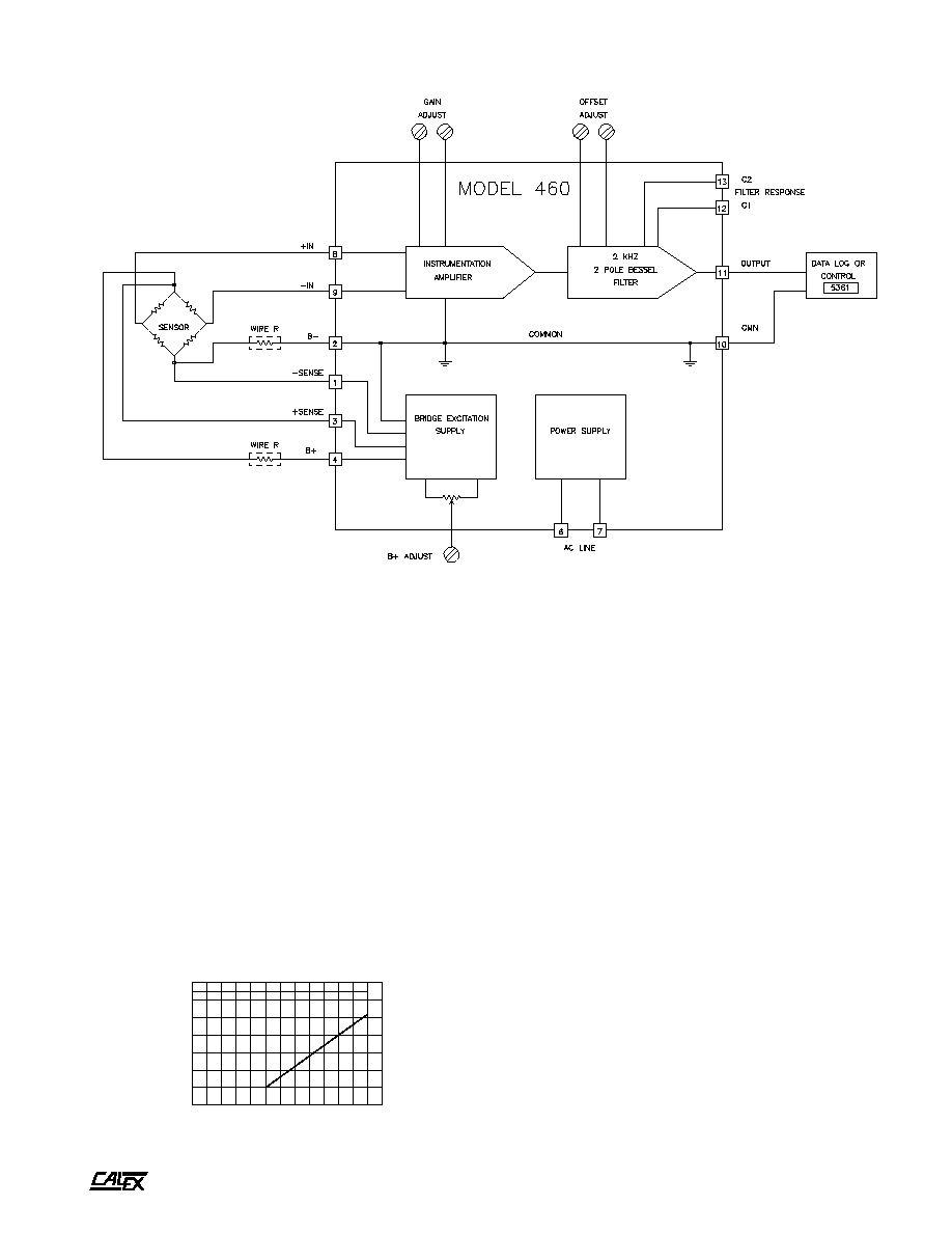
FIGURE 3. Typical Bridge Application
A
2401 Stanwell Drive ∑ Concord, California 94520 ∑ Ph: 925/687-4411 or 800/542-3355 ∑ Fax: 925/687-3333 ∑ www.calex.com ∑ Email: sales@calex.com
4
4/2001
Model 460 Bridgesensor
Typical Bridge Application
Figure 3 shows a typical bridge application using a standard
350 Ohm bridge. This could be a strain gage, load cell,
pressure transducer, accelerometer, or other bridge based
measurement.
Typical bridge output is 2 or 3 mV/Volt of excitation. With the
power supply excitation voltage at 10 Volts an output of 20 to
30 mV from the bridge can be obtained. The common mode
voltage of the bridge (the instrumentation amplifier input
signal level) is 5 Volts. This is well within the 6.5 Volt common
mode voltage range of the amplifier. The built-in potentiometer
set to a gain of 200 would achieve an output voltage of 4 to 6
Volts.
Assuming a standard 350 Ohm bridge is used, the current
required from the excitation supply (set at 10 Volts) would be
28.6mA. If the leads were long enough to have 10 Ohms of
internal resistance there would be a drop of over 0.286 Volts
in both the plus and common side of the bridge. To eliminate
this potential error (especially where the current might vary
during the course of a measurement) the sense lines are
connected to measure and regulate the voltage right at the
bridge rather than at the output of the supply. The decision to
use the sense leads or not depends entirely on the lead
length, its resistance, and the effect of that error on the
measurement.
Application Suggestions
The Model 460 is designed to eliminate many of the ordinary
problems associated with bridge type measurements. Since
the whole system is in one case the common problem of
ground loops or circulating currents caused by poor wiring
practices is eliminated. It is recommended that lead lengths
be kept to a minimum. The use of shielded twisted pairs for
the input leads is recommended for most applications.
To minimize self heating errors the use of minimum excitation
power is suggested as is sufficient heatsinking of the transducer
whenever possible. For optimum stability a one hour warm-
up is recommended. Avoid large temperature changes or
stray magnetic fields.
The Model 460 Bridgesensor is ready to wire into your system,
have power applied, and start making measurements for you.
Filter Roll Off Frequency
The table in Figure 4 shows the values for C1 and C2 to set
the 3 dB filter frequency. A printed circuit board is included for
convenient mounting of the two capacitors. Use X7R ceramic
or foil type capacitors.
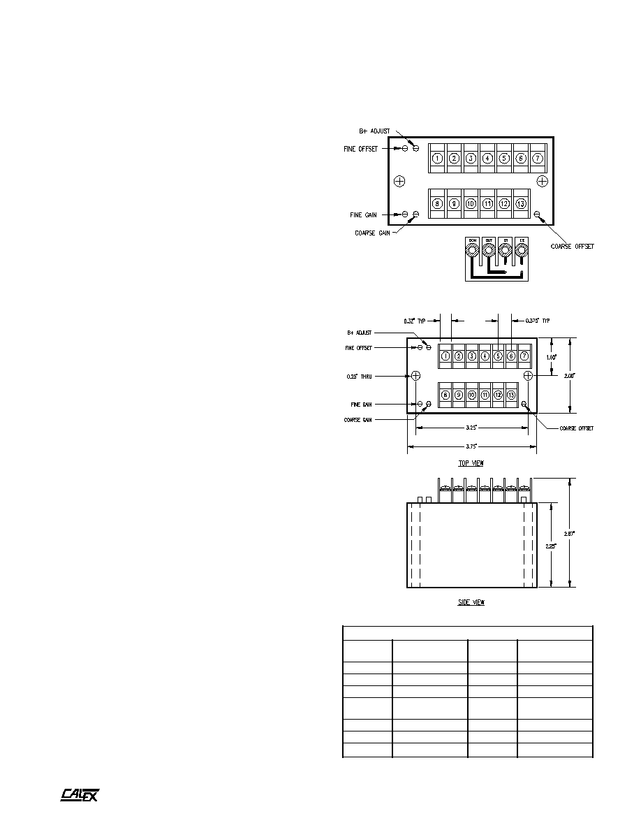
Mechanical Specifications
Specifically designed for rugged field use the Model 460 is
completely encapsulated in epoxy using a vacuum potting
system to insure a complete seal against corrosive
environments. It is similarly protected against shock and
vibration and will provide years of reliable and accurate
operation.
Filter
C1
C2
Frequency
To Pin 11
To Pin 10
2000 Hertz
None
None
200 Hertz
0.068 µF
0.022 µF
20 Hertz
0.68 µF
0.22 µF
9.4 Hertz
1.5 µF
0.47 µF
FIGURE 4. Filter Roll Off Frequency
FIGURE 5. Case Dimension
s
t
n
e
m
n
g
i
s
s
A
p
i
r
t
S
l
a
n
i
m
r
e
T
w
e
r
c
S
l
a
n
i
m
r
e
T
n
o
i
t
c
n
u
F
w
e
r
c
S
l
a
n
i
m
r
e
T
n
o
i
t
c
n
u
F
1
E
S
N
E
S
-
8
T
U
P
N
I
+
2
-
B
9
T
U
P
N
I
-
3
E
S
N
E
S
+
0
1
N
M
C
R
E
I
F
I
L
P
M
A
4
+
B
1
1
R
E
I
F
I
L
P
M
A
T
U
P
T
U
O
5
D
E
S
U
T
O
N
2
1
1
C
-
R
E
T
L
I
F
6
C
A
3
1
2
C
-
R
E
T
L
I
F
7
C
A