 | –≠–ª–µ–∫—Ç—Ä–æ–Ω–Ω—ã–π –∫–æ–º–ø–æ–Ω–µ–Ω—Ç: 48D12.500 | –°–∫–∞—á–∞—Ç—å:  PDF PDF  ZIP ZIP |
A
12 Watt Dual Series DC/DC Converters
Manufacturing Company, Inc. ∑ Concord, California 94520 ∑ Ph: 925/687-4411 or 800/542-3355 ∑ Fax: 925/687-3333 ∑ www.calex.com ∑ Email: sales@calex.com
1
4/8/99, STCO #970624-2, STCO #990408-1,
eco# 041007-1
1
2
3
4
5
+ OUTPUT
CMN
- OUTPUT
+ INPUT
- INPUT
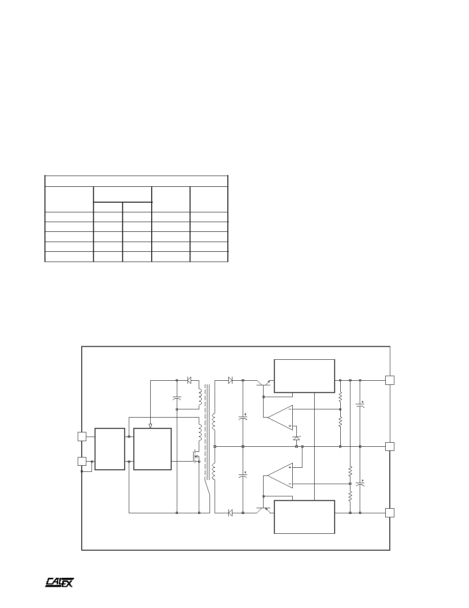
LC
INPUT
FILTER
PWM
CONTROL
PWM FEEDBACK
CROSS
COUPLED
FOLDBACK
CURRENT LIMIT
CROSS
COUPLED
FOLDBACK
CURRENT LIMIT
SHIELDED ISOLATION
TRANSFORMER
LOW TC
REFERENCE
100µF
100µF
SIX-SIDED SHIELDED STEEL CASE
Features
Low Noise Output
LC Type Input Filter
Six-Sided Shielded Steel Case
Very Wide Input Voltage Ranges
(9-36, 18-54, and 24-72)
High Efficiency Operation
Long Term Output Fault Survival
5 Year Warranty
12 Watt Dual Series Block Diagram
Description
These 10 and 12 Watt Dual Output DC/DC converters are
designed for telecommunications, medical or industrial
equipment and instrumentation systems. The converters
feature very wide input voltage ranges.
The converter consists of a hi-speed chopper circuit using
state of the art MOSFET technology, isolation transformer,
and high regulation linear post regulator. This provides for
very low noise and ultra stable output voltages.
t
r
a
h
C
n
o
i
t
c
e
l
e
S
l
e
d
o
M
e
g
n
a
R
t
u
p
n
I
C
D
V
s
t
u
p
t
u
O
C
D
V
s
t
u
p
t
u
O
A
m
N
I
M
X
A
M
0
0
5
.
2
1
D
4
2
0
0
.
9
0
0
.
6
3
0
.
2
1
±
0
0
5
±
0
0
4
.
5
1
D
4
2
0
0
.
9
0
0
.
6
3
0
.
5
1
±
0
0
4
±
0
0
0
1
.
5
D
8
2
0
0
.
8
1
0
0
.
4
5
0
.
5
±
0
0
0
1
±
0
0
5
.
2
1
D
8
4
0
0
.
4
2
0
0
.
2
7
0
.
2
1
±
0
0
5
±
0
0
4
.
5
1
D
8
4
0
0
.
4
2
0
0
.
2
7
0
.
5
1
±
0
0
4
±
A
12 Watt Dual Series DC/DC Converters
Manufacturing Company, Inc. ∑ Concord, California 94520 ∑ Ph: 925/687-4411 or 800/542-3355 ∑ Fax: 925/687-3333 ∑ www.calex.com ∑ Email: sales@calex.com
2
4/8/99, STCO #970624-2, STCO #990408-1,
eco# 041007-1
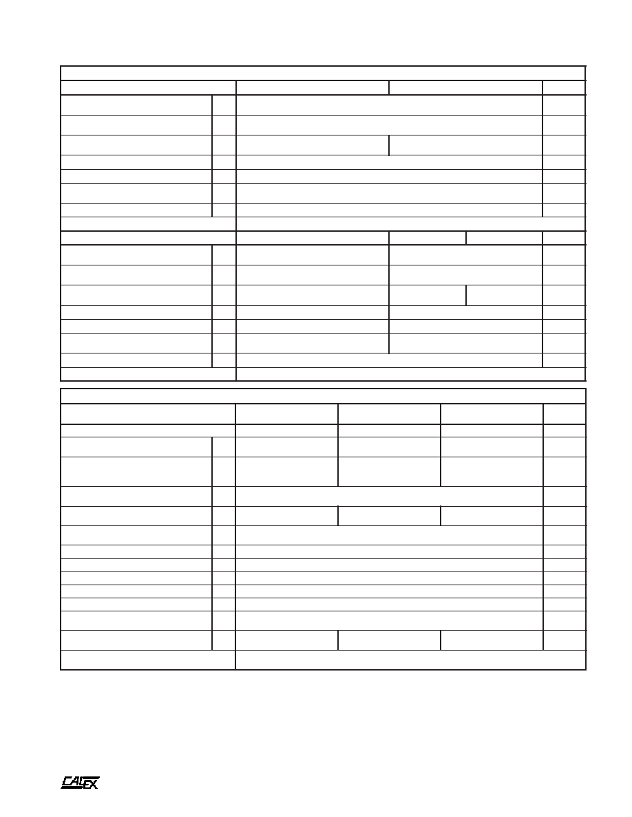
NOTES
*
All parameters measured at Tc=25∞C, nominal input voltage
and full rated load unless otherwise noted. Refer to the
CALEX Application Notes for the definition of terms,
measurement circuits and other information.
(2)
Determine the correct fuse size by calculating the maximum DC
current drain at low line input, maximum load then adding 20 to
25 percent.
(3)
No minimum load required.
(4)
Short term stability is specified after a 30 minute warm-up at full
load.
(5)
Transient response is defined as the time for the output to settle
from a 100% step load change to a 1% error band (rise time of
step = 2µSec).
(6)
Dynamic response is defined as the peak overshoot during a
transient as defined in note 5 above.
*
s
r
e
t
e
m
a
r
a
P
t
u
p
n
I
l
e
d
o
M
0
0
5
.
2
1
D
4
2
0
0
4
.
5
1
D
4
2
s
t
i
n
U
e
g
n
a
R
e
g
a
t
l
o
V
N
I
M
X
A
M
0
0
.
9
0
0
.
6
3
C
D
V
w
b
z
H
M
0
2
-
0
,
e
l
p
p
i
R
d
e
t
c
e
l
f
e
R
P
Y
T
X
A
M
0
2
5
4
P
-
P
A
m
d
a
o
L
ll
u
F
t
n
e
r
r
u
C
t
u
p
n
I
d
a
o
L
o
N
P
Y
T
P
Y
T
0
1
7
0
4
0
0
7
0
4
A
m
y
c
n
e
i
c
i
f
f
E
P
Y
T
0
7
%
y
c
n
e
u
q
e
r
F
g
n
i
h
c
t
i
w
S
P
Y
T
0
0
1
z
H
k
s
m
0
0
1
,
e
g
a
t
l
o
v
r
e
v
O
t
u
p
n
I
m
u
m
i
x
a
M
e
g
a
m
a
d
o
N
X
A
M
0
4
C
D
V
r
o
r
r
E
t
u
p
t
u
O
%
1
,
e
m
i
T
n
o
-
n
r
u
T
P
Y
T
0
6
s
m
e
s
u
F
d
e
d
n
e
m
m
o
c
e
R
)
2
(
l
e
d
o
M
0
0
0
1
.
5
D
8
2
0
0
5
.
2
1
D
8
4
0
0
4
.
5
1
D
8
4
s
t
i
n
U
e
g
n
a
R
e
g
a
t
l
o
V
N
I
M
X
A
M
0
0
.
8
1
0
0
.
4
5
0
0
.
4
2
0
0
.
2
7
C
D
V
w
b
z
H
M
0
2
-
0
,
e
l
p
p
i
R
d
e
t
c
e
l
f
e
R
P
Y
T
X
A
M
0
2
0
5
5
1
0
3
P
-
P
A
m
d
a
o
L
ll
u
F
t
n
e
r
r
u
C
t
u
p
n
I
d
a
o
L
o
N
P
Y
T
P
Y
T
0
0
6
0
4
0
6
3
4
2
0
5
3
4
2
A
m
y
c
n
e
i
c
i
f
f
E
P
Y
T
0
6
0
7
%
y
c
n
e
u
q
e
r
F
g
n
i
h
c
t
i
w
S
P
Y
T
7
8
0
0
1
z
H
k
s
m
0
0
1
,
e
g
a
t
l
o
v
r
e
v
O
t
u
p
n
I
m
u
m
i
x
a
M
e
g
a
m
a
d
o
N
X
A
M
0
6
0
8
C
D
V
r
o
r
r
E
t
u
p
t
u
O
%
1
,
e
m
i
T
n
o
-
n
r
u
T
P
Y
T
0
6
s
m
e
s
u
F
d
e
d
n
e
m
m
o
c
e
R
)
2
(
*
s
r
e
t
e
m
a
r
a
P
t
u
p
t
u
O
L
E
D
O
M
0
0
0
1
.
5
D
8
2
0
0
5
.
2
1
D
4
2
0
0
5
.
2
1
D
8
4
0
0
4
.
5
1
D
4
2
0
0
4
.
5
1
D
8
4
s
t
i
n
U
e
g
a
t
l
o
V
t
u
p
t
u
O
5
±
2
1
±
5
1
±
C
D
V
)
3
(
t
n
e
r
r
u
C
d
e
t
a
R
N
I
M
X
A
M
0
0
0
9
-
/
0
0
1
1
+
0
0
0
5
±
0
0
0
4
±
A
m
e
g
n
a
R
e
g
a
t
l
o
V
d
a
o
L
%
0
0
1
N
I
M
P
Y
T
X
A
M
5
9
.
4
0
0
.
5
5
0
.
5
0
9
.
1
1
0
0
.
2
1
0
1
.
2
1
0
9
.
4
1
0
0
.
5
1
0
1
.
5
1
C
D
V
e
c
n
a
l
a
B
t
u
p
t
u
O
)
d
a
o
L
ll
u
F
,
t
u
p
t
u
O
s
u
n
i
M
o
t
s
u
l
P
(
P
Y
T
X
A
M
6
.
0
0
.
1
%
d
a
o
L
%
0
0
1
-
0
n
o
i
t
a
l
u
g
e
R
d
a
o
L
P
Y
T
X
A
M
5
0
.
0
0
1
.
0
2
0
.
0
7
0
.
0
2
0
.
0
7
0
.
0
%
n
o
i
t
a
l
u
g
e
R
e
n
i
L
C
D
V
x
a
M
-
n
i
M
=
n
i
V
P
Y
T
X
A
M
2
0
.
0
7
0
.
0
%
)
4
(
y
t
il
i
b
a
t
S
m
r
e
T
t
r
o
h
S
P
Y
T
2
0
.
0
%
y
t
il
i
b
a
t
S
m
r
e
T
g
n
o
L
P
Y
T
3
.
0
s
r
H
k
/
%
)
5
(
e
s
n
o
p
s
e
R
t
n
e
i
s
n
a
r
T
P
Y
T
0
2
s
µ
)
6
(
e
s
n
o
p
s
e
R
c
i
m
a
n
y
D
P
Y
T
0
2
k
a
e
p
V
m
)
7
(
n
o
i
t
c
e
j
e
R
e
l
p
p
i
R
t
u
p
n
I
P
Y
T
0
6
B
d
w
b
z
H
M
0
2
-
0
,
e
s
i
o
N
P
Y
T
X
A
M
0
1
0
4
P
-
P
V
m
t
n
e
i
c
i
f
f
e
o
C
e
r
u
t
a
r
e
p
m
e
T
P
Y
T
X
A
M
0
0
1
0
0
3
0
5
0
5
1
0
5
0
5
1
C
∞
/
m
p
p
o
t
n
o
i
t
c
e
t
o
r
P
t
i
u
c
r
i
C
t
r
o
h
S
s
t
u
p
t
u
O
ll
a
r
o
f
n
o
m
m
o
C
t
i
m
i
L
t
n
e
r
r
u
C
m
u
m
i
n
i
M
s
r
u
o
H
8
,
s
u
o
u
n
i
t
n
o
C
A
12 Watt Dual Series DC/DC Converters
Manufacturing Company, Inc. ∑ Concord, California 94520 ∑ Ph: 925/687-4411 or 800/542-3355 ∑ Fax: 925/687-3333 ∑ www.calex.com ∑ Email: sales@calex.com
3
4/8/99, STCO #970624-2, STCO #990408-1,
eco# 041007-1
n
i
P
n
o
i
t
c
n
u
F
1
T
U
P
N
I
+
2
T
U
P
N
I
-
3
T
U
P
T
U
O
+
4
N
M
C
5
T
U
P
T
U
O
-
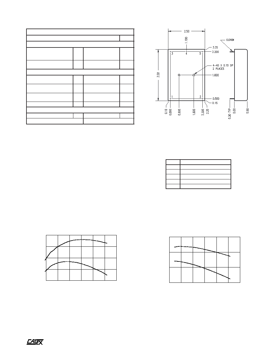
BOTTOM VIEW
SIDE VIEW
Mechanical tolerances unless otherwise noted:
X.XX dimensions: ±0.020 inches
X.XXX dimensions: ±0.005 inches
Typical Performance (Tc=25∞C, Full Rated Load).
20
30
40
50
60
70
80
LINE INPUT (VOLTS)
60
65
70
75
EFFICIENCY (%)
48D15.400 EFFICIENCY Vs. LINE INPUT
50% FULL LOAD
100% FULL LOAD
(7)
The input ripple rejection is specified for DC to 120Hz ripple with
a modulation amplitude of 1% of Vin.
(8)
The functional temperature range is intended to give an additional
data point for use in evaluating this power supply. At the low
functional temperature the power supply will function with no
side effects, however sustained operation at the high functional
temperature will reduce expected operational life. The data
sheet specifications are not guaranteed over the functional
temperature range.
(9)
The case thermal impedance is specified as the case temperature
rise over ambient per package watt dissipated.
(10) Water Washability - Calex DC/DC converters are designed to
withstand most solder/wash processes. Careful attention should
be used when assessing the applicability in your specific
manufacturing process. Converters are not hermetically sealed.
*
s
n
o
i
t
a
c
i
f
i
c
e
p
S
l
a
r
e
n
e
G
s
l
e
d
o
M
l
l
A
s
t
i
n
U
n
o
i
t
a
l
o
s
I
e
g
a
t
l
o
V
n
o
i
t
a
l
o
s
I
e
g
a
k
a
e
L
A
µ
0
1
t
u
p
t
u
O
-
t
u
p
n
I
N
I
M
0
0
5
C
D
V
t
u
p
t
u
O
o
t
t
u
p
n
I
e
c
n
a
t
i
c
a
p
a
C
P
Y
T
0
2
1
F
p
l
a
t
n
e
m
n
o
r
i
v
n
E
e
g
n
a
R
g
n
i
t
a
r
e
p
O
e
s
a
C
g
n
i
t
a
r
e
D
o
N
N
I
M
X
A
M
5
2
-
0
8
C
∞
)
8
(
e
g
n
a
R
l
a
n
o
i
t
c
n
u
F
e
s
a
C
N
I
M
X
A
M
0
4
-
5
8
C
∞
e
g
n
a
R
e
g
a
r
o
t
S
N
I
M
X
A
M
5
5
-
0
0
1
C
∞
)
9
(
e
c
n
a
d
e
p
m
I
l
a
m
r
e
h
T
P
Y
T
6
t
t
a
W
/
C
∞
l
a
r
e
n
e
G
t
h
g
i
e
W
t
i
n
U
P
Y
T
5
.
6
z
o
s
t
i
K
g
n
i
t
n
u
o
M
V
D
B
8
0
-
5
1
2
K
M
&
2
2
0
-
5
1
2
K
M
10
15
20
25
30
35
40
LINE INPUT (VOLTS)
64
66
68
70
72
EFFICIENCY (%)
24D15.400 EFFICIENCY Vs. LINE INPUT
50% FULL LOAD
100% FULL LOAD
A
12 Watt Dual Series DC/DC Converters
Manufacturing Company, Inc. ∑ Concord, California 94520 ∑ Ph: 925/687-4411 or 800/542-3355 ∑ Fax: 925/687-3333 ∑ www.calex.com ∑ Email: sales@calex.com
4
4/8/99, STCO #970624-2, STCO #990408-1,
eco# 041007-1
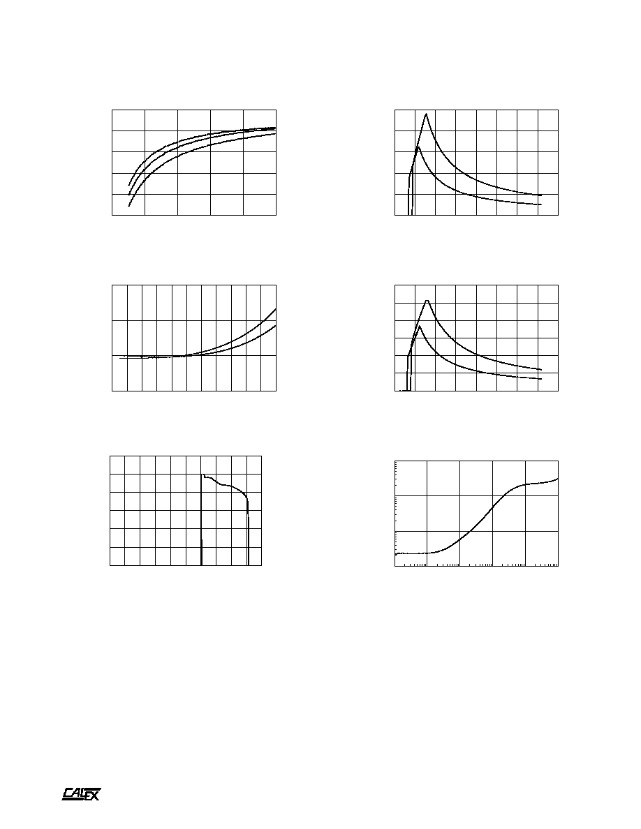
Typical Performance (Tc=25∞C, Full Rated Load).
0
5
10
15
20
25
30
35
40
LINE INPUT (VOLTS)
0.00
0.50
1.00
1.50
2.00
2.50
INPUT CURRENT (AMPS)
24D INPUT CURRENT Vs. LINE INPUT
50% RATED LOAD
100% RATED LOAD
0
10
20
30
40
50
60
70
80
LINE INPUT (VOLTS)
0.0
0.2
0.4
0.6
0.8
1.0
1.2
INPUT CURRENT (AMPS)
48D INPUT CURRENT Vs. LINE INPUT
50% RATED LOAD
100% RATED LOAD
0
20
40
60
80
100
LOAD (%)
30
40
50
60
70
80
EFFICIENCY (%)
48D15.400 EFFICIECNY Vs. LOAD
LINE = 24VDC
LINE = 48VDC
LINE = 72VDC
-30
-20
-10
0
10
20
30
40
50
60
70
80
CASE TEMPERATURE (Deg C)
-0.1
0.0
0.1
0.2
NORMALIZED OUTPUT (%)
OUTPUT VOLTAGE Vs CASE TEMPERATURE
POSITIVE OUTPUT
NEGATIVE OUTPUT
0
20
40
60
80
100
120
140
160
180
200
OUTPUT LOAD (%)
0
20
40
60
80
100
120
OUTPUT VOLTAGE (%)
OUTPUT VOLTAGE Vs. OUTPUT LOAD
+ OUTPUT
- OUTPUT
FREQUENCY (Hz)
.001
.01
.1
1
IMPEDANCE (OHMS)
OUTPUT IMPEDANCE Vs. FREQUENCY
10
100
1K
10K
100K
1M