A
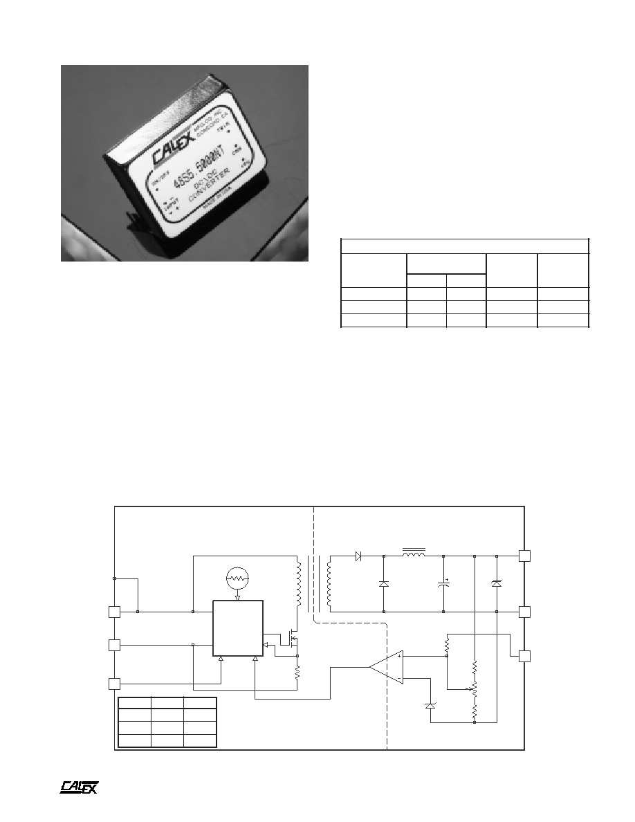
30 Watt NT Single Series DC/DC Converters
2401 Stanwell Drive ∑ Concord, California 94520 ∑ Ph: 925/687-4411 or 800/542-3355 ∑ Fax: 925/687-3333 ∑ www.calex.com ∑ Email: sales@calex.com
1
eco# 041007-1
FIVE-SIDED SHIELDED COPPER CASE
CURRENT
MODE
PWM
THERMAL SHUTDOWN
SHIELDED
ISOLATION TRANSFORMER
ISOLATED
FEEDBACK
LOW TC
BANDGAP REFERENCE
3
2
1
+ INPUT
- INPUT
ON/OFF
4
5
6
+ OUTPUT
CMN
TRIM
C
D
t
r
a
h
C
n
o
i
t
c
e
l
e
S
l
e
d
o
M
e
g
n
a
R
t
u
p
n
I
C
D
V
t
u
p
t
u
O
C
D
V
t
u
p
t
u
O
A
m
n
i
M
x
a
M
T
N
0
0
0
5
.
5
S
8
4
*
0
.
6
3
0
.
2
7
0
.
5
0
0
0
5
T
N
0
0
5
2
.
2
1
S
8
4
0
.
6
3
0
.
2
7
0
.
2
1
0
0
5
2
T
N
0
0
0
2
.
5
1
S
8
4
0
.
6
3
0
.
2
7
0
.
5
1
0
0
0
2
0
5
9
0
6
L
U
/
A
S
C
:
s
l
a
v
o
r
p
p
A
y
c
n
e
g
A
*
Features
Only 2.02" x 1.62" x 0.55" high
-40∞ to +90∞C case operating range standard
Very low OFF current, 1 mA typically
Transient overvoltage protected output
Overcurrent and overtemperature protection
Up to 86% efficiency
5 Year Warranty
Description
These single output DC/DC converters are designed to provide
a wide range of PCB mount power solutions. The wide 2:1
input voltage range covers the common American and
European telecom standards.
For flexibility, a trim pin is included to adjust the output
voltage. Use it to compensate for voltage drops in your
system's wiring or to achieve non standard voltages. Use the
remote ON/OFF function to maximize battery life.
The NT Single Series continues the CALEX tradition of
reliable design by including transient overvoltage suppressor
diode protection at the output terminals. Also provided as
standard are overcurrent and overtemperature protection
circuits. These features assure zero failure rate operation
when using the NT Single Series. All CALEX products are
backed by a 5 Year Warranty.
25 - 30 Watt NT Single Series Block Diagram
t
u
p
t
u
O
C
D
5
F
µ
0
7
2
V
8
.
6
2
1
F
µ
0
4
V
5
1
5
1
F
µ
0
4
V
8
1
A
30 Watt NT Single Series DC/DC Converters
2401 Stanwell Drive ∑ Concord, California 94520 ∑ Ph: 925/687-4411 or 800/542-3355 ∑ Fax: 925/687-3333 ∑ www.calex.com ∑ Email: sales@calex.com
2
eco# 041007-1
*
s
r
e
t
e
m
a
r
a
P
t
u
p
t
u
O
l
e
d
o
M
T
N
0
0
0
5
.
5
S
8
4
T
N
0
0
5
2
.
2
1
S
8
4
T
N
0
0
0
2
.
5
1
S
8
4
s
t
i
n
U
e
g
a
t
l
o
V
t
u
p
t
u
O
5
2
1
5
1
C
D
V
)
3
(
d
a
o
L
d
e
t
a
R
N
I
M
X
A
M
0
5
2
1
0
0
0
5
5
2
6
0
0
5
2
0
0
5
0
0
0
2
A
m
e
g
n
a
R
e
g
a
t
l
o
V
d
a
o
L
%
0
0
1
N
I
M
P
Y
T
X
A
M
0
5
9
.
4
0
0
0
.
5
0
5
0
.
5
0
0
9
.
1
1
0
0
0
.
2
1
0
0
1
.
2
1
0
0
9
.
4
1
0
0
0
.
5
1
0
0
1
.
5
1
C
D
V
n
o
i
t
a
l
u
g
e
R
d
a
o
L
d
a
o
L
ll
u
F
x
a
M
-
n
i
M
P
Y
T
X
A
M
5
.
0
0
.
1
2
.
0
0
.
1
2
.
0
0
.
1
%
n
o
i
t
a
l
u
g
e
R
e
n
i
L
C
D
V
x
a
M
-
n
i
M
=
n
i
V
P
Y
T
X
A
M
2
.
0
0
.
1
%
)
4
(
y
t
il
i
b
a
t
S
m
r
e
T
t
r
o
h
S
P
Y
T
2
0
.
0
<
%
y
t
il
i
b
a
t
S
m
r
e
T
g
n
o
L
P
Y
T
5
0
.
0
<
s
r
H
k
/
%
)
5
(
e
s
n
o
p
s
e
R
t
n
e
i
s
n
a
r
T
P
Y
T
5
2
1
0
0
2
0
0
2
s
µ
)
6
(
e
s
n
o
p
s
e
R
c
i
m
a
n
y
D
P
Y
T
0
8
0
0
3
0
0
3
k
a
e
p
V
m
)
7
(
n
o
i
t
c
e
j
e
R
e
l
p
p
i
R
t
u
p
n
I
P
Y
T
0
6
B
d
)
8
(
w
b
z
H
M
0
2
-
0
,
e
s
i
o
N
P
Y
T
e
g
a
t
l
o
v
t
u
p
t
u
o
f
o
%
1
P
-
P
V
m
t
n
e
i
c
i
f
f
e
o
C
e
r
u
t
a
r
e
p
m
e
T
P
Y
T
X
A
M
0
5
0
5
1
C
∞
/
m
p
p
p
m
a
l
C
e
g
a
t
l
o
v
r
e
v
O
P
Y
T
8
.
6
5
1
8
1
C
D
V
o
t
n
o
i
t
c
e
t
o
r
P
t
i
u
c
r
i
C
t
r
o
h
S
s
t
u
p
t
u
O
ll
a
r
o
f
n
o
m
m
o
C
d
n
a
g
n
i
t
i
m
il
t
n
e
r
r
u
c
h
t
i
w
n
o
i
t
c
e
t
o
r
p
s
u
o
u
n
i
t
n
o
c
s
e
d
i
v
o
r
P
s
e
u
q
i
n
h
c
e
t
d
a
o
l
r
e
v
o
l
a
m
r
e
h
t
NOTES
*
All parameters measured at Tc=25 ∞C case temperature,
nominal input voltage and full rated load unless otherwise
noted. Refer to the CALEX Application Notes for definition
of terms, measurement circuits and other information.
(2)
See our application note on fusing DC/DC converters.
(3)
Minimum load required for rated regulation only. Module will not
be damaged if run at less than minimum load.
(4)
Short term stability is specified after a 30 minute warm-up at
full load, and with constant line, load and ambient conditions.
(5)
The transient response is specified as the time required to settle
from 50 to 75% step load change (rise time of step = 20µSec.)
to a 1% error band.
(6)
Dynamic response is the peak overshoot voltage during the
transient response time defined in note 5.
(7)
The input ripple rejection is specified for DC to 120Hz ripple with
a modulation amplitude of 1% Vin.
(8)
Noise is measured per CALEX Application Notes. Output
noise is measured with a 0.01µF ceramic connected directly
across the output pins.
(9)
The ON/OFF pin is Open Collector TTL, CMOS, and relay
compatible. The input to this pin is referenced to Pin 2, -Input
and is protected to +100 VDC.
(10) Case is tied to Pin 3, +Input.
(11) Full output trim range may not be available at full load and
minimum input voltage. Full trim is guaranteed from minimum
input voltage +5% and full load.
(12) The case thermal impedance is specified as the case
temperature rise over ambient per package watt dissipated.
(13) Specifications subject to change without notice.
(14) Water Washability - Calex DC/DC converters are designed to
withstand most solder/wash processes. Careful attention should
be used when assessing the applicability in your specific
manufacturing process. Converters are not hermetically sealed.
*
s
r
e
t
e
m
a
r
a
P
t
u
p
n
I
l
e
d
o
M
T
N
0
0
0
5
.
5
S
8
4
T
N
0
0
5
2
.
2
1
S
8
4
T
N
0
0
0
2
.
5
1
S
8
4
s
t
i
n
U
e
g
n
a
R
e
g
a
t
l
o
V
N
I
M
P
Y
T
X
A
M
0
.
6
3
0
.
8
4
0
.
2
7
C
D
V
d
a
o
L
ll
u
F
t
n
e
r
r
u
C
t
u
p
n
I
d
a
o
L
o
N
P
Y
T
P
Y
T
0
3
6
4
0
3
7
4
0
3
7
4
A
m
y
c
n
e
i
c
i
f
f
E
P
Y
T
4
8
6
8
6
8
%
y
c
n
e
u
q
e
r
F
g
n
i
h
c
t
i
w
S
P
Y
T
0
0
2
z
H
k
,
e
g
a
t
l
o
v
r
e
v
O
t
u
p
n
I
m
u
m
i
x
a
M
e
g
a
m
a
D
o
N
s
m
0
0
1
X
A
M
5
8
C
D
V
e
m
i
T
n
o
-
n
r
u
T
P
Y
T
0
1
s
m
e
s
u
F
d
e
d
n
e
m
m
o
c
e
R
)
2
(
A
30 Watt NT Single Series DC/DC Converters
2401 Stanwell Drive ∑ Concord, California 94520 ∑ Ph: 925/687-4411 or 800/542-3355 ∑ Fax: 925/687-3333 ∑ www.calex.com ∑ Email: sales@calex.com
3
eco# 041007-1
SIZE TRACES FOR 1 AMP DC
MAXIMUM
FUSE
C1
TO INPUT
SOURCE
LOAD
SIZE TRACES
APPROPRIATELY FOR
LOAD REQUIREMENTS
*
PINS 1 AND 6 MAY BE LEFT FLOATING
IF NOT USED
*
*
3
2
1
6
5
4
+ INPUT
- INPUT
ON/OFF
+ OUTPUT
CMN
TRIM
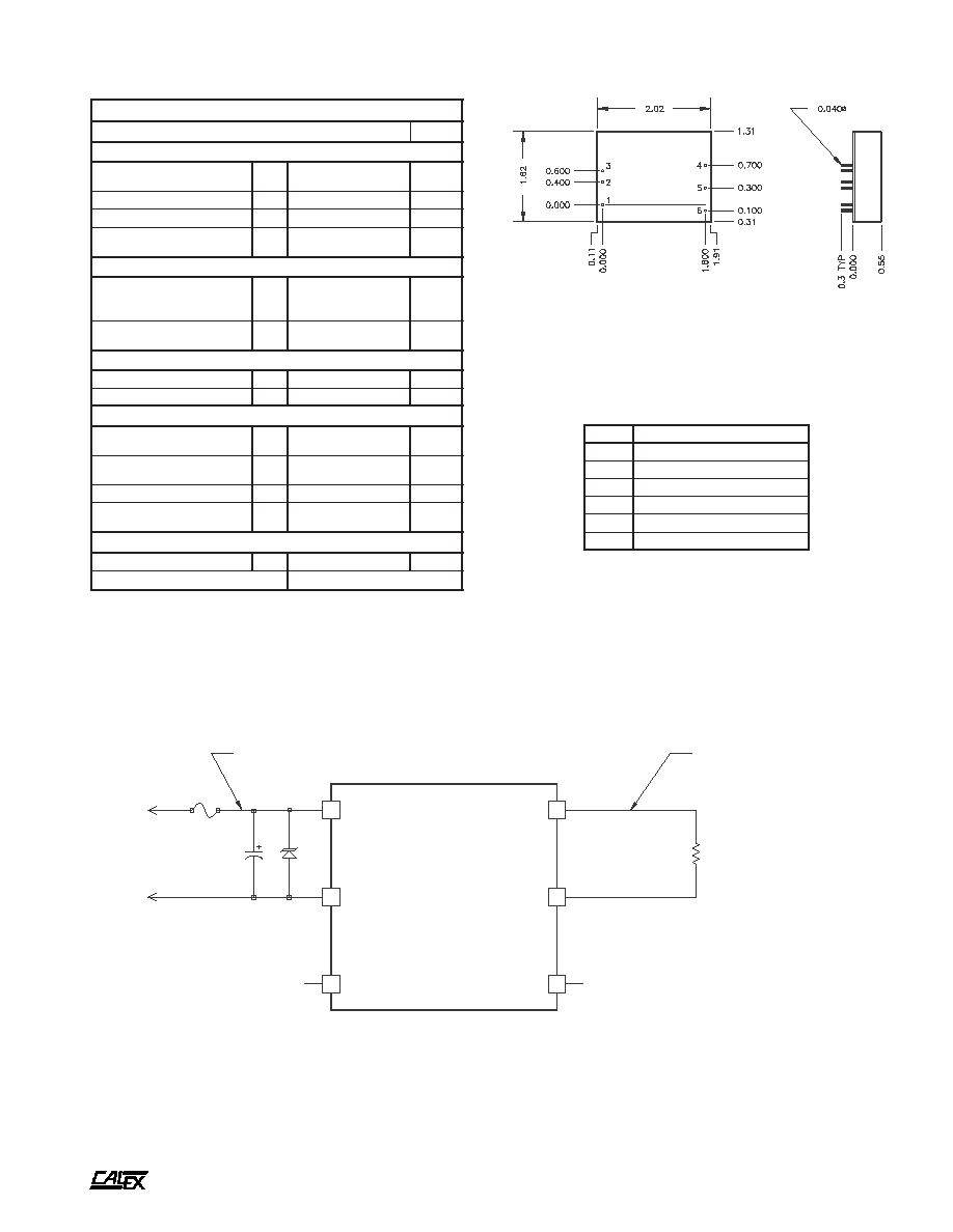
D1
C1 - Is required for proper operation, see text
D1 - Overvoltage clamp is optional, see text
n
i
P
n
o
i
t
c
n
u
F
1
F
F
O
/
N
O
2
T
U
P
N
I
-
3
T
U
P
N
I
+
4
T
U
P
T
U
O
+
5
N
M
C
6
M
I
R
T
Mechanical tolerances unless otherwise noted:
X.XX dimensions: ±0.020 inches
X.XXX dimensions: ±0.005 inches
Seal around terminals is not hermetic. Do not immerse units in any
liquid.
Figure 1. Recommended application circuit for NT Single Series
BOTTOM VIEW
SIDE VIEW
25-30 Watt NT Single Typical Application
Figure 1 shows the recommended connections for the NT
Singles. Capacitor C1 is required for proper operation (see
below). The trim and ON/OFF pins can be safely left floating
if they are not used. The input fuse should not be omitted.
The fuse prevents unlimited current from flowing in the
case of a catastrophic system failure, and also protects the
DC/DC converter input circuit.
*
s
n
o
i
t
a
c
i
f
i
c
e
p
S
l
a
r
e
n
e
G
s
l
e
d
o
M
l
l
A
s
t
i
n
U
)
9
(
n
o
i
t
c
n
u
F
F
F
O
/
N
O
l
e
v
e
L
c
i
g
o
L
N
O
n
e
p
O
n
i
P
e
v
a
e
L
r
o
N
I
M
0
.
8
C
D
V
l
e
v
e
L
c
i
g
o
L
F
F
O
X
A
M
0
.
2
C
D
V
e
c
n
a
t
s
i
s
e
R
t
u
p
n
I
P
Y
T
0
0
1
s
m
h
o
k
t
n
e
r
r
u
C
e
l
d
I
r
e
t
r
e
v
n
o
C
w
o
L
n
i
P
F
F
O
/
N
O
P
Y
T
1
<
A
m
n
o
i
t
a
l
o
s
I
)
0
1
(
e
g
a
t
l
o
V
n
o
i
t
a
l
o
s
I
e
g
a
k
a
e
L
A
µ
0
1
t
u
p
t
u
O
-
t
u
p
n
I
N
I
M
4
4
5
1
C
D
V
t
u
p
t
u
O
o
t
t
u
p
n
I
e
c
n
a
t
i
c
a
p
a
C
P
Y
T
0
0
3
F
p
n
o
i
t
c
n
u
F
m
i
r
T
t
u
p
t
u
O
e
c
n
a
t
s
i
s
e
R
t
u
p
n
I
P
Y
T
0
2
s
m
h
o
k
)
1
1
(
e
g
n
a
R
g
n
i
m
m
a
r
g
o
r
P
N
I
M
5
±
%
l
a
t
n
e
m
n
o
r
i
v
n
E
e
g
n
a
R
g
n
i
t
a
r
e
p
O
e
s
a
C
g
n
i
t
a
r
e
D
o
N
N
I
M
X
A
M
0
4
-
0
9
+
C
∞
e
g
n
a
R
e
g
a
r
o
t
S
N
I
M
X
A
M
5
5
-
0
0
1
C
∞
)
2
1
(
e
c
n
a
d
e
p
m
I
l
a
m
r
e
h
T
P
Y
T
0
1
t
t
a
W
/
C
∞
n
w
o
d
t
u
h
S
l
a
m
r
e
h
T
e
r
u
t
a
r
e
p
m
e
T
e
s
a
C
P
Y
T
0
0
1
C
∞
l
a
r
e
n
e
G
t
h
g
i
e
W
t
i
n
U
P
Y
T
9
.
1
z
o
t
i
K
g
n
i
t
n
u
o
M
s
i
s
s
a
h
C
8
S
M

A
30 Watt NT Single Series DC/DC Converters
2401 Stanwell Drive ∑ Concord, California 94520 ∑ Ph: 925/687-4411 or 800/542-3355 ∑ Fax: 925/687-3333 ∑ www.calex.com ∑ Email: sales@calex.com
4
eco# 041007-1
Sizing The Input Capacitor
For maximum reliability the NT Single Series must use a
capacitor of sufficient ripple handling capability connected
across the input pins. The probable result of undersizing (over
stressing) this capacitor is increased self heating, shortening
of the capacitors and hence shortening of your systems' life.
Oversizing the capacitor can have a negative effect on your
product's cost and size, although this kind of overdesign does
not result in shorter life of any components. There is no one
optimum value for this capacitor. The size and capacity are
dependent on the following factors:
1) Expected ambient temperature and your temperature
derating guidelines
2) Your ripple current derating guidelines
3) The maximum anticipated load on the converter
4) The minimum input voltage expected on the converter
5) The statistical probability that your system will spend a
significant amount of time at any worst case extreme
Factors 1 and 2 are determined by your system design
guidelines. These can range from 50% to 100% of the
manufacturer's rated maximum, although a usual derating
factor is 70% of manufacturer's maximum limit. 70% derating
means that if the capacitor manufacturer says their capacitor
can do 1 A RMS and 100 VDC you would not use the part over
700 mA RMS and 70 VDC. Surge voltage rating should also
be evaluated against any expected voltage surges when
selecting a capacitor working voltage.
Factors 3 and 4 realistically determine the worst case ripple
current. The reflected ripple current increases with output
load and increases as the input voltage decreases. So if you
are running with a solid 48 VDC input and at 50% load your
capacitors required ripple current rating would decrease by
more than 2:1 from what would be required for operation at 36
VDC with full load (see the "Input Reflected Ripple" curve).
Factor 5 is not easy to quantify. At CALEX, we can make
no assumptions about a customer's system so we design for
continuous operation at worst case extremes.
Example Of Capacitor Sizing
Given the following conditions, select the minimum size
capacitor needed to provide reliable performance:
Converter ........................................ 48S5.5000NT
Minimum Input Voltage ................... Voltage 40 VDC
Maximum Input Voltage .................. Voltage 52 VDC
Maximum Load ............................... 5 Amps
Maximum Ambient Temperature .... 40∞C
Your Capacitor Voltage
Derating Guideline ............... 70% of Maximum
Specification
Your Capacitor Current
Derating Guideline ............... 70% of Maximum
Specification
(40∞ C ambient + 5∞ C for self heating)
A capacitor selection can now be made. Look only at
controlled low ESR types (where the ESR is specified as a
maximum) because these usually have the highest ripple
current capability per unit volume.
Be careful to compare apples to apples. Some
manufacturers specify their capacitors at 85∞C and others
specify at 105∞C. The manufacturers give temperature derating
guidelines so all capacitors should be normalized to your
maximum ambient (plus 5∞C to account for self heating)
before making a selection. Since the NT Single Series operates
at 200 kHz the frequency usually does not have to be derated
since most modern low ESR capacitors are rated at 100 kHz
or more.
One note: The temperature derating multipliers are based
on the capacitor's expected life at 105∞C. The life of a
capacitor operating at a significantly lower temperature will
not be greater if the ripple current in the part is increased over
the 105∞C rating. This means that a capacitor rated for 1 A
RMS current at 105∞C and 2 A RMS at 50∞C will have the same
life if used at either point while the same capacitor used at 1
A RMS and 50∞C will have a longer life.
Suggested Capacitor Sources
Suitable capacitors can be acquired from the following sources:
United Chemi-Con SXE, RXC, RZ and RZA Series
Suggested Part:
SXE100VB221M12.5X35LL
220µF, 100V, 105∞C Rated
ESR=0.087 Ohms
Allowable Ripple=1.04 A @ 105∞C
Nichicon
PR and PF
Suggested Part:
UPR100102MPHRH
1000µF, 100V, 105∞C Rated
ESR=0.047 Ohms
Allowable Ripple=1.32 A @ 105∞C
Panasonic
HFE Series
Suggested Part:
ECEA2AFE221L
220µF, 100V, 105∞C Rated
ESR=0.089 Ohms
Allowable Ripple=1.04 A @ 105∞C
Solution
According to the NT Single Series "Reflected Input Ripple Vs.
Line Input" curve at 40 VDC input and 5 Amps output (100%
of rated load), the reflected input ripple can be read as 975 mA
RMS. From the derating guidelines the capacitor's rated
voltage and ripple current can be determined.
Capacitor voltage rating is calculated as:
1
V =
Voltage Derating Factor
x
Maximum Expected Input
1
V =
0.7
x 52 = 74
Volts or greater
1
I = Current Derating Factor x Reflected Ripple
1
=
0.7
x 975
mA = 1.39 A RMS or greater at 45∞C
A
30 Watt NT Single Series DC/DC Converters
2401 Stanwell Drive ∑ Concord, California 94520 ∑ Ph: 925/687-4411 or 800/542-3355 ∑ Fax: 925/687-3333 ∑ www.calex.com ∑ Email: sales@calex.com
5
eco# 041007-1
4
6
5
4
6
5
10K LOAD
LOAD
+ OUT
TRIM
CMN
+ OUT
TRIM
CMN
USING TRIMPOT
USING FIXED RESISTORS
TRIM
DOWN
TRIM
UP
L1
C1
C2
C3
4
5
+ OUTPUT
CMN
L1 = 5µH
C1, C3 = 0.01µF, CERAMIC
C2 = 10µF/35V, TANTALUM
THIS CAPACITOR IS REQUIRED
FOR PROPER OPERATION
FUSE
20 µH, 1000 mA
TO INPUT
SOURCE
3
2
+ INPUT
- INPUT
10 µF
100 V
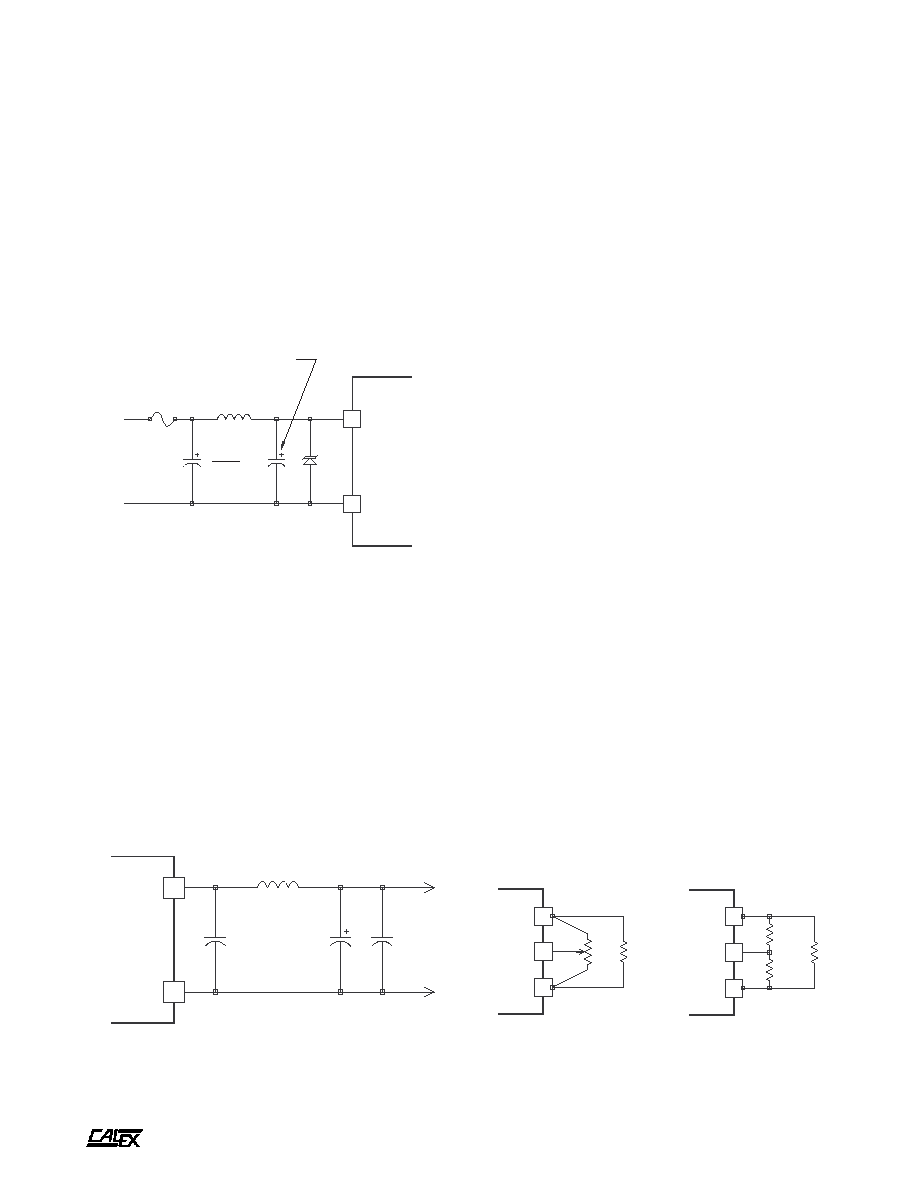
Figure 3. Low noise output filter circuit
Figure 4. Output trim methods
The suggested capacitors will work for any line and load
condition, however, they may be oversized for your application.
High ripple current film capacitors may also be used and may
provide longer life or smaller size.
Low Noise Input Filtering Circuit
To reduce the input reflected ripple to less than 100 mA peak-
to-peak the circuit shown in Figure 2 may be used. Use
reasonable caution when selecting an inductor other than the
one specified. Nearly any 105∞C rated capacitor can be used
for the 10µF / 100V part. To prevent input filter peaking the
ESR should be in the range of 0.5 to 2 ohms. Do not use the
lowest ESR capacitor available for this part. This will render
the filter ineffective.
Figure 2. Low noise input filter circuit
Input Overvoltage Protection
As shown in figure 1, optional transient overvoltage protection
may be used at the input of the converter. This should be
considered if your application circuit could present a voltage
greater than the NT Series maximum transient voltage listed
on the data sheet. This device could also serve as a reverse
input voltage protector if used with a suitable fuse.
Low Noise Output Filtering Circuit
Extra output filtering is easy with the NT Series due to the high,
constant 200 kHz switching frequency. The optional circuit
shown in figure 3 can reduce the output noise to 15 mV p-p on
a 5 Volt output converter and 40 mV p-p on 12 and 15 Volt
output converters. The inductor should be sized appropriately
for your maximum load current. No extra large capacitance is
required on the output of the converter other than the
components shown and the standard bypassing on your PCB.
Large, low ESR capacitors on the output of the converter can
actually make the output noise worse or cause oscillation.
See the CALEX application note on "Understanding Output
Impedance" for more information.
Remote ON/OFF Circuit Operation
The remote ON/OFF pin is best applied as follows:
To turn the unit off, the ON/OFF pin should be tied to the -
Input pin. This is best done by an open collector arrangement
or contact closure.
To turn the unit on, let the ON/OFF pin float.
If the remote ON/OFF pin is not used, it may be safely left
floating. There is a 100K internal pull-up resistor inside the
unit to +9 Volts DC.
Other applications of the ON/OFF function can be found in
the application note, "Understanding the Remote ON/OFF
Function".
Proper Application Of The Trim Pin
The trim pin is used to adjust the output voltage slightly to
compensate for voltage drops in the system's wiring. Figure
4 shows the proper application of the trim pin. Either a 10K
trimpot or fixed resistors may be used.
Other applications for the TRIM function can be found in the
CALEX application note, "Applying the Remote Sense and
Trim Functions on DC/DC Converters."
Use one resistor for either trim up or trim down. The values
can range from infinity to zero ohms with zero ohms providing
the most trim.
A
30 Watt NT Single Series DC/DC Converters
2401 Stanwell Drive ∑ Concord, California 94520 ∑ Ph: 925/687-4411 or 800/542-3355 ∑ Fax: 925/687-3333 ∑ www.calex.com ∑ Email: sales@calex.com
6
eco# 041007-1
5.2, 8.5 and 10 Volt Output Applications
The NT series can be adjusted easily for other non-standard
output voltages. To get a 5.2 Volt output use a 5 Volt output
converter and trim the output up to 5.2 Volts. To get either a
8.5, 9 or 10 Volt output use a 12 Volt output converter and trim
the output down (12 Volt NT converters typically trim down to
8.5 Volts).
The output power must be limited to either 25 or 30 Watts
when trimming the output up (the output current must be
reduced to keep a constant power output). When trimming the
output down, the output current must be kept at or below the
maximum current listed for that model.
Temperature Derating Guidelines
Care must be taken in the application of all power devices. Be
sure to account for the self heating in your instrument due to
the power converter and the loads. For minimum temperature
gradient, the hottest components should be mounted at the
bottom of your system (bottom of a vertical PCB) and the
coolest components at the top of the system. This will help to
even the temperature of the entire system and prevent
temperature gradients.
The NT Single Series has a thermal impedance of 10∞C per
package Watt dissipated. During normal operation the NT
Single Series can be expected to run at 86% efficiency at 48
VDC and full load. This means that the NT Single Series is
dissipating nearly 5 Watts internally at full load. This, therefore,
translates to a package temperature rise of 50∞C (10∞C/Watt
x 5 Watts dissipated).
The maximum rated case temperature for the NT Series is
90∞C. This means that, in the absence of other heat sources
(including the load that the converter is powering) and with at
least 3 inches of clearance, the NT Single Series can be
expected to operate at full load in an ambient temperature of
40∞C.
Additional heat sinks or cooling air flow can extend the
ambient temperature of operation significantly.
In the event of system cooling blockage or failure, the
thermal shut-off of the NT Single Series will prevent any
catastrophic power converter failure. When the ambient
temperature cools below the thermal limit temperature the NT
Single Series will re-start.
0
10
20
30
40
50
60
70
80
LINE INPUT (VOLTS)
0.0
0.2
0.4
0.6
0.8
1.0
1.2
1.4
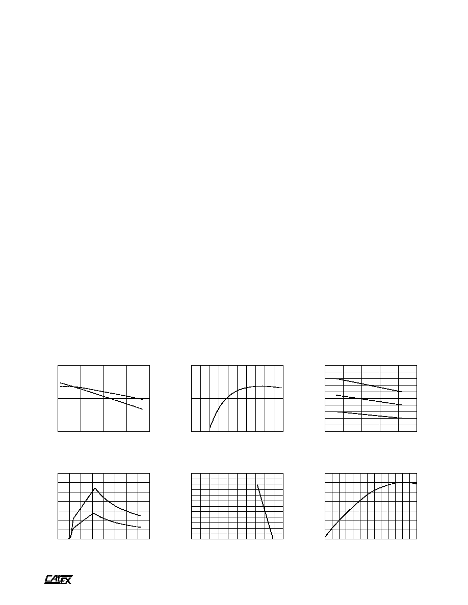
INPUT CURRENT (AMPS)
INPUT CURRENT Vs. LINE INPUT VOLTAGE
100% LOAD
50% LOAD
0
10
20
30
40
50
60
70
80
90
100
LOAD (%)
80
85
90
EFFICIENCY(%)
EFFICIENCY Vs. LOAD
0
20
40
60
80
100
120
140
160
180
200
OUTPUT LOAD (%)
0
10
20
30
40
50
60
70
80
90
100
110
120
OUTPUT VOLTAGE (%)
OUTPUT VOLTAGE Vs. OUTPUT LOAD
30
40
50
60
70
80
LINE INPUT (VDC)
0.2
0.3
0.4
0.5
0.6
0.7
0.8
0.9
1.0
1.1
1.2
INPUT RIPPLE (A RMS)
INPUT RIPPLE CURRENT Vs. LINE INPUT VOLTAGE
100% LOAD
75% LOAD
50% LOAD
-40
-30
-20
-10
0
10
20
30
40
50
60
70
80
90
CASE TEMPERATURE (Deg C)
-0.5
-0.4
-0.3
-0.2
-0.1
-0.0
0.1
0.2
NORMALIZED OUTPUT (%)
OUTPUT VOLTAGE Vs CASE TEMPERATURE
Typical Performance (Tc=25∞C, Vin=Nom VDC, Rated Load).
35
45
55
65
75
LINE INPUT (VDC)
80
85
90
EFFICIENCY (%)
EFFICIENCY Vs. LINE INPUT VOLTAGE
100% LOAD
50% LOAD