A
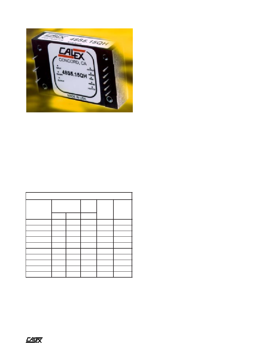
75 Watt QH Single Series DC/DC Converters
2401 Stanwell Drive ∑ Concord, California 94520 ∑ Ph: 925/687-4411 or 800/542-3355 ∑ Fax: 925/687-3333 ∑ www.calex.com ∑ Email: sales@calex.com
1
eco#: 050503-1, 050713-2, 060414-4, 060615-3
Features
Small size 1.45"x2.28"x0.52",
industry standard 1/4 brick
Excellent thermal performance with metal baseplate
High Efficiency
Fast over voltage protection
Pulse-by-pulse current limiting, dead short
current limiting
Over-temperature protection
Auto-softstart
Very Low noise
Low profile magnetics run cooler
Constant frequency for normal operation
2:1 input voltage range
Remote Sense with excellent regulation
Remote ON/OFF
Super energy saving, 6 mA input idle current
Output trim with very low temperature coefficient
Water Washable, wide humidity applications
Good shock and vibration damping
Low cost
5 Year Warranty
Description
The 75 Watt single QH series of DC/DC Converters provide
precisely regulated dc outputs. All outputs are fully isolated
from the inputs, allowing the output to be used with positive or
negative polarity and various grounding options. The QH
Series meets the most rigorous requirments in an industry
standard case size for industrial process control and telecom
applications.
Standard features include remote sensing, output trim, and
remote on/off. Threaded-through holes are provided to allow
easy mounting or add a heat sink for extended temperature
use.
t
r
a
h
C
n
o
i
t
c
e
l
e
S
l
e
d
o
M
e
g
n
a
R
t
u
p
n
I
C
D
V
n
i
I
@
C
D
A
m
o
n
t
u
o
V
C
D
V
t
u
o
I
C
D
A
n
i
M
x
a
M
p
y
T
H
Q
0
2
.
3
S
4
2
8
1
6
3
5
3
.
3
3
.
3
0
2
H
Q
5
1
.
5
S
4
2
8
1
6
3
2
7
.
3
5
5
1
H
Q
6
.
2
1
S
4
2
8
1
6
3
3
6
.
3
2
1
5
2
.
6
H
Q
5
.
5
1
S
4
2
8
1
6
3
9
5
.
3
5
1
5
H
Q
3
.
4
2
S
4
2
8
1
6
3
9
5
.
3
4
2
3
1
.
3
H
Q
0
2
.
3
S
8
4
6
3
5
7
7
6
.
1
3
.
3
0
2
H
Q
5
1
.
5
S
8
4
6
3
5
7
6
8
.
1
5
5
1
H
Q
6
.
2
1
S
8
4
6
3
5
7
1
8
.
1
2
1
5
2
.
6
H
Q
5
.
5
1
S
8
4
6
3
5
7
9
7
.
1
5
1
5
H
Q
3
.
4
2
S
8
4
6
3
5
7
9
7
.
1
4
2
3
1
.
3
.
e
v
i
t
i
s
o
p
s
i
c
i
g
o
l
F
F
O
/
N
O
t
l
u
a
f
e
D
.
c
i
g
o
l
F
F
O
/
N
O
e
v
i
t
a
g
e
n
r
e
d
r
o
o
t
r
e
b
m
u
n
l
e
d
o
m
e
h
t
o
t
N
-
d
d
A
A
75 Watt QH Single Series DC/DC Converters
2401 Stanwell Drive ∑ Concord, California 94520 ∑ Ph: 925/687-4411 or 800/542-3355 ∑ Fax: 925/687-3333 ∑ www.calex.com ∑ Email: sales@calex.com
2
eco#: 050503-1, 050713-2, 060414-4, 060615-3
Unless otherwise stated, these specifications apply for ambient temperature T
A
=23 ±2∞C, nominal input voltage, and rated full load. (1)
s
r
e
t
e
m
a
r
a
P
t
u
p
n
I
l
e
d
o
M
H
Q
0
2
.
3
S
4
2
H
Q
5
1
.
5
S
4
2
H
Q
6
.
2
1
S
4
2
H
Q
5
.
5
1
S
4
2
H
Q
3
.
4
2
S
4
2
s
t
i
n
U
e
g
n
a
R
e
g
a
t
l
o
V
N
I
M
P
Y
T
X
A
M
8
1
4
2
6
3
C
D
V
*
e
g
a
t
l
o
v
r
e
v
O
t
u
p
n
I
c
e
S
m
0
0
1
X
A
M
0
5
C
D
V
n
o
i
t
c
e
j
e
R
e
l
p
p
i
R
t
u
p
n
I
)
z
H
0
2
1
(
P
Y
T
0
6
B
d
t
u
o
k
c
o
L
e
g
a
t
l
o
v
r
e
d
n
U
s
e
Y
n
o
i
t
c
e
t
o
r
P
e
g
a
t
l
o
V
e
s
r
e
v
e
R
t
u
p
n
I
s
e
Y
d
a
o
L
o
N
t
n
e
r
r
u
C
t
u
p
n
I
d
a
o
L
%
0
0
1
P
Y
T
P
Y
T
0
5
4
.
3
0
5
7
.
3
0
5
6
.
3
0
5
6
.
3
0
5
6
.
3
A
m
A
t
n
e
r
r
u
C
h
s
u
r
n
I
X
A
M
2
.
0
A
2
S
H
µ
2
1
,
e
l
p
p
i
R
d
e
t
c
e
l
f
e
R
)
3
(
e
c
n
a
d
e
p
m
I
e
c
r
u
o
S
P
Y
T
0
1
P
-
P
A
m
y
c
n
e
i
c
i
f
f
E
P
Y
T
2
8
4
8
6
8
7
8
7
8
%
y
c
n
e
u
q
e
r
F
g
n
i
h
c
t
i
w
S
P
Y
T
0
6
3
z
H
k
e
s
u
F
d
e
d
n
e
m
m
o
c
e
R
)
2
(
S
P
M
A
s
r
e
t
e
m
a
r
a
P
t
u
p
n
I
l
e
d
o
M
H
Q
0
2
.
3
S
8
4
H
Q
5
1
.
5
S
8
4
H
Q
6
.
2
1
S
8
4
H
Q
5
.
5
1
S
8
4
H
Q
3
.
4
2
S
8
4
s
t
i
n
U
e
g
n
a
R
e
g
a
t
l
o
V
N
I
M
P
Y
T
X
A
M
6
3
8
4
5
7
C
D
V
*
e
g
a
t
l
o
v
r
e
v
O
t
u
p
n
I
c
e
S
m
0
0
1
X
A
M
5
8
C
D
V
n
o
i
t
c
e
j
e
R
e
l
p
p
i
R
t
u
p
n
I
)
z
H
0
2
1
(
P
Y
T
0
6
B
d
t
u
o
k
c
o
L
e
g
a
t
l
o
v
r
e
d
n
U
s
e
Y
n
o
i
t
c
e
t
o
r
P
e
g
a
t
l
o
V
e
s
r
e
v
e
R
t
u
p
n
I
s
e
Y
d
a
o
L
o
N
t
n
e
r
r
u
C
t
u
p
n
I
d
a
o
L
%
0
0
1
P
Y
T
P
Y
T
0
8
7
.
1
0
8
9
.
1
0
8
8
.
1
0
8
8
.
1
0
8
8
.
1
A
m
A
t
n
e
r
r
u
C
h
s
u
r
n
I
X
A
M
2
.
0
A
2
S
H
µ
2
1
,
e
l
p
p
i
R
d
e
t
c
e
l
f
e
R
)
3
(
e
c
n
a
d
e
p
m
I
e
c
r
u
o
S
P
Y
T
0
1
P
-
P
A
m
y
c
n
e
i
c
i
f
f
E
P
Y
T
2
8
4
8
6
8
7
8
7
8
%
y
c
n
e
u
q
e
r
F
g
n
i
h
c
t
i
w
S
P
Y
T
0
6
3
z
H
k
e
s
u
F
d
e
d
n
e
m
m
o
c
e
R
)
2
(
S
P
M
A
* Absolute Maximum Ratings. Caution: Stresses in excess of the Absolute Maximum Ratings can cause permanent damage to the device (see Note 1).

A
75 Watt QH Single Series DC/DC Converters
2401 Stanwell Drive ∑ Concord, California 94520 ∑ Ph: 925/687-4411 or 800/542-3355 ∑ Fax: 925/687-3333 ∑ www.calex.com ∑ Email: sales@calex.com
3
eco#: 050503-1, 050713-2, 060414-4, 060615-3
Unless otherwise stated, these specifications apply for ambient temperature T
A
=23 ±2∞C, nominal input voltage, and rated full load. (1)
NOTES:
(1)
Refer to the CALEX Application Notes for the definition of terms,
measurement circuits, and other information.
(2)
Refer to the CALEX Application Notes for information on fusing.
For inrush current, refer to the specifications above.
(3)
Place a 33 µF capacitor between the two "Input" pins. Then place
a current sensor in series with a 12 µH inductor between the
capacitor and the source. The reflected ripple current is
measured over 5 Hz to 20 MHz bandwidth (current sensor is
located between the converter input pins and the 12 µH inductor).
(4)
Optimum performance is obtained when this power supply is
operated within the minimum to maximum load specifications.
No damage to module will occur when the output is operated at
less than minimum load, but the output voltage may contain a
low frequency component that may exceed output noise
specifications.
At no load the converter output voltage will fall out of regulation,
typically rising to the OVP limit. A load current of between 0.5%
to 1% of maximum rated load will usually suffice to bring the
output voltage within regulation.
(5)
Load regulation is defined as the output voltage change when
changing load current from maximum to minimum. The voltage
is measured at the output pin.
(6)
Load Transient Recovery Time is defined as the time for the
output to settle from a 50 to 75% or 25% step load change to a
1% error band of output voltage (rise time of step = 2µSec).
(7)
Load Transient Overshoot is defined as the peak overshoot
during a transient as defined in the Note 6 above.
(8)
Noise is measured per the CALEX Application Notes. Output
noise is measured with a 10 µF tantalum capacitor in parallel
with a 0.1 µF ceramic capacitor connected across the output to
CMN. Measurement bandwidth is 0-20 MHz.
(9)
When an external On/Off switch is used, such as open collector
switch, logic high requires the switch to be high-impedance.
Switch leakage currents greater than 20 µA may be sufficient to
trigger the On/Off to the logic-low state.
(10) Most switches would be suitable for logic On/Off control, in case
there is a problem, you can make following estimation and then
leave some margin.
When open collector is used for logic high, "Open Circuit Voltage
at On/Off Pin", "Output Resistance" and "External Leakage
Current Allowed for Logic High" are used to estimate the high
impedance requirement of open collector.
When switch is used for logic low, "Open Circuit Voltage at On/
Off Pin", "Output Resistance" and "LOW Logic Level" are used
to estimate the low impedance requirement of switch.
(11) Thermal impedance is tested with the converter mounted vertically
and facing another printed circuit board 1/2 inch away. If
converter is mounted horizontally with no obstructions, thermal
impedance is approximately 10 ∞C/W.
If heat sink is needed, apply a very thin layer of thermally
conductive grease on the metal base of converter, then properly
tighten the screws.
(12) Water Washability - Calex DC/DC converters are designed to
withstand most solder/wash processes. Careful attention should
be used when assessing the applicability in your specific
manufacturing process. Converters are not hermetically sealed.
(13) Torque fasteners into threaded mounting inserts at 12 in. oz. or
less. Greater torque may result in damage to unit and void the
warranty.
s
r
e
t
e
m
a
r
a
P
t
u
p
t
u
O
l
e
d
o
M
H
Q
0
2
.
3
S
4
2
H
Q
0
2
.
3
S
8
4
H
Q
5
1
.
5
S
4
2
H
Q
5
1
.
5
S
8
4
H
Q
6
.
2
1
S
4
2
H
Q
6
.
2
1
S
8
4
H
Q
5
.
5
1
S
4
2
H
Q
5
.
5
1
S
8
4
H
Q
3
.
4
2
S
4
2
H
Q
3
.
4
2
S
8
4
s
t
i
n
U
e
g
a
t
l
o
V
t
u
p
t
u
O
3
.
3
5
2
1
5
1
4
2
C
D
V
e
g
a
t
l
o
V
t
u
p
t
u
O
y
c
a
r
u
c
c
A
t
n
i
o
p
t
e
S
X
A
M
1
±
%
t
o
o
h
s
r
e
v
O
n
O
n
r
u
T
P
Y
T
0
%
t
n
e
i
c
i
f
f
e
o
C
e
r
u
t
a
r
e
p
m
e
T
P
Y
T
X
A
M
5
0
0
.
0
1
0
.
0
3
0
0
.
0
5
0
0
.
0
C
∞
/
%
)
8
(
e
s
i
o
N
P
Y
T
0
2
0
2
0
4
0
5
0
7
V
m
S
M
R
e
l
p
p
i
R
P
Y
T
0
3
0
3
5
7
0
0
1
0
5
1
P
-
P
V
m
)
4
(
t
n
e
r
r
u
C
d
a
o
L
N
I
M
X
A
M
5
0
0
1
%
t
o
o
h
s
r
e
v
O
t
n
e
i
s
n
a
r
T
d
a
o
L
)
7
(
P
Y
T
2
%
y
r
e
v
o
c
e
R
t
n
e
i
s
n
a
r
T
d
a
o
L
)
6
(
e
m
i
T
P
Y
T
8
.
0
c
e
S
m
)
5
(
n
o
i
t
a
l
u
g
e
R
d
a
o
L
d
a
o
L
x
a
M
-
n
i
M
P
Y
T
X
A
M
2
0
.
0
2
.
0
%
n
o
i
t
a
l
u
g
e
R
e
n
i
L
x
a
M
-
n
i
M
=
n
i
V
P
Y
T
X
A
M
1
0
.
0
1
.
0
%
n
o
i
t
c
e
t
o
r
P
e
g
a
t
l
o
v
r
e
v
O
)
P
V
O
(
d
l
o
h
h
s
e
r
h
T
g
n
i
h
c
t
a
l
-
n
o
N
-
e
p
y
T
P
V
O
e
g
a
t
l
o
v
r
e
v
O
p
o
o
L
n
e
p
O
p
m
a
l
C
N
I
M
X
A
M
5
1
1
5
3
1
%
t
i
m
i
L
t
n
e
r
r
u
C
t
u
p
t
u
O
m
o
n
-
t
u
o
V
f
o
%
0
9
=
t
u
o
V
P
Y
T
0
2
1
%
t
n
e
r
r
u
C
t
i
u
c
r
i
C
t
r
o
h
S
t
u
p
t
u
O
V
1
.
0
=
t
u
o
V
P
Y
T
0
6
1
%
A
75 Watt QH Single Series DC/DC Converters
2401 Stanwell Drive ∑ Concord, California 94520 ∑ Ph: 925/687-4411 or 800/542-3355 ∑ Fax: 925/687-3333 ∑ www.calex.com ∑ Email: sales@calex.com
4
eco#: 050503-1, 050713-2, 060414-4, 060615-3
s
n
o
i
t
a
c
i
f
i
c
e
p
S
l
a
r
e
n
e
G
s
l
e
d
o
M
l
l
A
s
t
i
n
U
n
o
i
t
c
n
u
F
F
F
O
/
N
O
e
t
o
m
e
R
l
e
v
e
L
c
i
g
o
L
H
G
I
H
n
i
P
F
F
O
/
N
O
e
v
a
e
L
r
o
n
e
p
O
N
I
M
0
.
3
C
D
V
t
n
e
r
r
u
C
e
g
a
k
a
e
L
l
a
n
r
e
t
x
E
)
9
(
h
g
i
H
c
i
g
o
L
r
o
f
d
e
w
o
ll
A
X
A
M
0
2
A
µ
n
o
i
t
c
e
t
o
r
P
e
d
o
i
D
t
u
p
n
I
e
g
a
t
l
o
V
X
A
M
0
5
C
D
V
l
e
v
e
L
c
i
g
o
L
W
O
L
t
u
p
n
I
-
o
t
n
i
P
F
F
O
/
N
O
e
i
T
r
o
X
A
M
0
.
1
C
D
V
c
i
g
o
L
r
o
f
t
n
e
r
r
u
C
g
n
i
k
n
i
S
w
o
L
X
A
M
1
A
m
t
a
e
g
a
t
l
o
V
t
i
u
c
r
i
C
n
e
p
O
)
0
1
(
n
i
P
F
F
O
/
N
O
y
r
a
m
i
r
P
c
i
g
o
L
e
v
i
t
i
s
o
P
c
i
g
o
L
e
v
i
t
a
g
e
N
P
Y
T
P
Y
T
6
.
5
5
.
1
C
D
V
C
D
V
t
n
e
r
r
u
C
e
l
d
I
)
F
F
O
s
i
e
l
u
d
o
M
(
P
Y
T
6
C
D
A
m
r
o
r
r
e
%
1
o
t
e
m
i
T
n
o
-
n
r
u
T
P
Y
T
8
c
e
S
m
n
o
i
t
p
O
c
i
g
o
L
e
v
i
t
i
s
o
P
N
O
e
l
u
d
o
M
-
H
G
I
H
F
F
O
e
l
u
d
o
M
-
W
O
L
n
o
i
t
p
O
c
i
g
o
L
e
v
i
t
a
g
e
N
F
F
O
e
l
u
d
o
M
-
H
G
I
H
N
O
e
l
u
d
o
M
-
W
O
L
m
i
r
T
e
g
a
t
l
o
V
t
u
p
t
u
O
e
g
n
a
R
m
i
r
T
N
I
M
X
A
M
0
1
±
f
o
%
t
u
o
V
e
c
n
a
t
s
i
s
e
R
t
u
p
n
I
P
Y
T
0
1
m
h
O
k
e
g
a
t
l
o
V
t
i
u
c
r
i
C
n
e
p
O
P
Y
T
5
.
2
V
g
n
i
s
n
e
S
e
t
o
m
e
R
e
g
a
t
l
o
V
t
u
p
t
u
O
s
p
o
r
D
e
g
a
t
l
o
V
m
u
m
i
x
a
M
d
a
e
L
n
o
X
A
M
5
.
0
C
D
V
n
o
i
t
a
l
u
g
e
R
e
n
i
L
g
n
i
s
n
e
s
e
t
o
m
e
r
r
e
d
n
u
P
Y
T
X
A
M
2
0
.
0
1
.
0
%
n
o
i
t
a
l
u
g
e
R
d
a
o
L
g
n
i
s
n
e
s
e
t
o
m
e
r
r
e
d
n
u
P
Y
T
X
A
M
5
0
.
0
2
.
0
%
t
i
m
i
L
m
i
r
T
d
n
a
e
s
n
e
S
e
g
a
t
l
o
V
t
u
p
t
u
O
m
u
m
i
x
a
M
X
A
M
0
1
1
f
o
%
t
u
o
V
n
o
i
t
a
l
o
s
I
*
n
o
i
t
a
l
o
s
I
t
u
p
t
u
O
o
t
t
u
p
n
I
e
g
a
k
a
e
L
A
µ
0
1
s
l
e
d
o
m
V
4
2
=
m
o
n
V
s
l
e
d
o
m
V
8
4
=
m
o
n
V
X
A
M
X
A
M
0
0
7
4
4
5
1
C
D
V
C
D
V
l
a
t
n
e
m
n
o
r
i
v
n
E
e
r
o
c
ll
e
B
,
F
B
T
M
d
e
t
a
l
u
c
l
a
C
1
e
s
a
C
,
1
d
o
h
t
e
M
0
0
0
,
0
0
0
,
1
>
r
H
g
n
i
t
a
r
e
p
O
e
t
a
l
p
e
s
a
B
e
g
n
a
R
e
r
u
t
a
r
e
p
m
e
T
N
I
M
X
A
M
0
4
-
0
0
1
C
∞
e
r
u
t
a
r
e
p
m
e
T
e
g
a
r
o
t
S
N
I
M
X
A
M
0
4
-
0
2
1
C
∞
)
1
1
(
e
c
n
a
d
e
p
m
I
l
a
m
r
e
h
T
P
Y
T
9
W
/
C
∞
n
w
o
d
t
u
h
S
l
a
m
r
e
h
T
e
r
u
t
a
r
e
p
m
e
T
e
t
a
l
p
e
s
a
B
)
t
r
a
t
s
e
R
o
t
u
A
(
N
I
M
P
Y
T
0
0
1
0
1
1
C
∞
l
a
r
e
n
e
G
n
o
i
s
n
e
m
i
D
e
s
a
C
"
2
5
.
0
x
"
5
4
.
1
x
"
8
2
.
2
g
n
i
d
n
e
P
s
l
a
v
o
r
p
p
A
y
c
n
e
g
A
0
5
9
0
6
L
U
C
/
L
U
t
i
K
g
n
i
t
n
u
o
M
s
i
s
s
a
h
C
8
1
S
M
s
t
r
e
s
n
I
g
n
i
t
n
u
o
M
n
o
e
u
q
r
o
T
X
A
M
.
z
o
.
n
i
2
1
n
i
P
n
o
i
t
c
n
u
F
1
T
U
P
N
I
-
2
F
F
O
/
N
O
3
T
U
P
N
I
+
4
T
U
P
T
U
O
-
5
E
S
N
E
S
-
6
M
I
R
T
7
E
S
N
E
S
+
8
T
U
P
T
U
O
+
* Absolute Maximum Ratings. Caution: Stresses in excess of the Absolute
Maximum Ratings can cause permanent damage to the device (see Note 1).
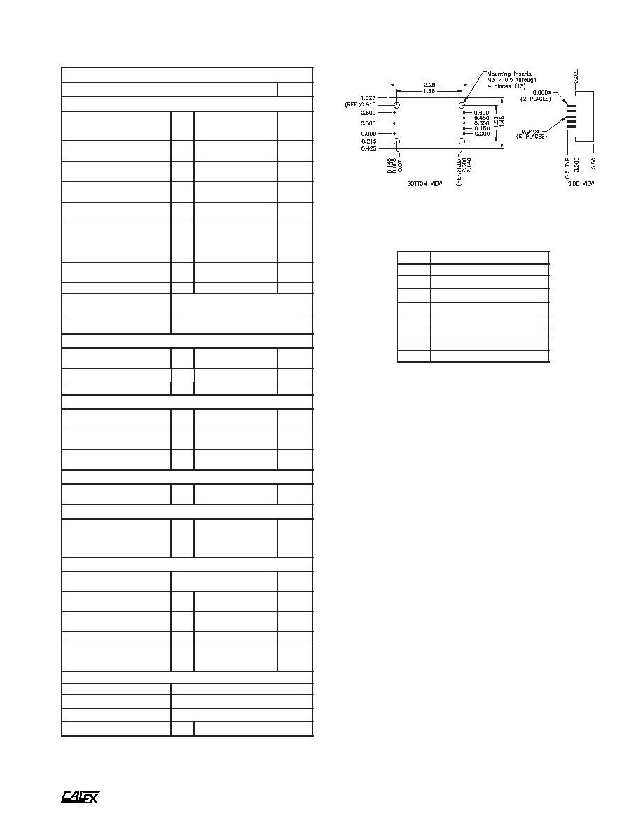
1
2
3
4
5
6
7
8
Mechanical tolerances unless otherwise noted:
X.XX dimensions: ±0.020 inches
X.XXX dimensions: ±0.005 inches