
A
5 to 7.5 Watt FW Single Series DC/DC Converters
Manufacturing Company, Inc. ∑ Concord, California 94520 ∑ Ph: 925/687-4411 or 800/542-3355 ∑ Fax: 925/687-3333 ∑ www.calex.com ∑ Email: sales@calex.com
1
STCO#970521-2,
eco# 041007-1
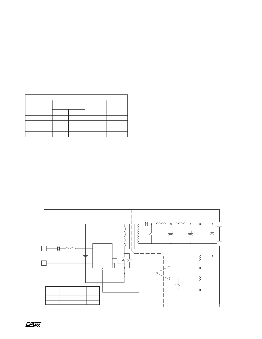
CURRENT
MODE
PWM
BANDGAP REFERENCE
ISOLATION TRANSFORMER
THERMAL SHUTDOWN
1
2
+ INPUT
- INPUT
3
5
+ OUTPUT
CMN
Features
Low noise outputs, 70 mV P-P maximum
Very low reflected ripple, 50 mA P-P maximum
Excellent regulation from no load to full load 0.2%
maximum
Excellent line regulation, 0.1% maximum
Efficiencies to 82%
Six-sided shielded low thermal gradient copper case
Five Year Warranty
7.5 Watt FW Single Series Block Diagram
Description
The low voltage FW single output converters are designed for
ultra wide input range, low noise industrial and instrument
applications requiring low input operating voltages. The wide
input range (3:1) is ideal for battery or unregulated input
applications.
These converters are state-of-the-art 100 kHz designs that
provide outstanding line and load regulation with efficiencies
approaching 82%.
The single outputs are regulated with a high loop gain
current mode control method that provides linear regulator
type performance with a true, high efficiency switching DC/DC
topology. The large amount of loop gain also insures excellent
input ripple rejection and line transient response.
All converters in this series are protected from output short
circuit, thermal overload and overvoltage transients on the
input and output.
t
r
a
h
C
n
o
i
t
c
e
l
e
S
l
e
d
o
M
e
g
n
a
R
t
u
p
n
I
C
D
V
t
u
p
t
u
O
C
D
V
t
u
p
t
u
O
A
m
N
I
M
X
A
M
W
F
0
0
5
1
.
5
S
2
1
9
7
2
5
0
0
5
1
W
F
5
2
6
.
2
1
S
2
1
9
7
2
2
1
5
2
6
W
F
0
0
5
.
5
1
S
2
1
9
7
2
5
1
0
0
5
A
5 to 7.5 Watt FW Single Series DC/DC Converters
Manufacturing Company, Inc. ∑ Concord, California 94520 ∑ Ph: 925/687-4411 or 800/542-3355 ∑ Fax: 925/687-3333 ∑ www.calex.com ∑ Email: sales@calex.com
2
STCO#970521-2,
eco# 041007-1
NOTES:
*
All Parameters measured at Tc=25∞C, nominal input voltage
and full rated load unless otherwise noted. Refer to the
CALEX Application Notes for the definition of terms,
measurement circuits and other information.
(2)
Noise is measured per CALEX Application Notes. Measurement
bandwidth is 0-20 MHz.
(3)
Determine the correct fuse size by referring to CALEX Application
Notes.
(4)
Case is tied to Pin 5, - Output.
(5)
Short term stability is specified after a 30 minute warmup at full
load, constant line and recording the drift over a 24 hour period.
(6)
The transient response is specified as the time required to settle
from a 50 to 75 % step load change (rise time of step = 2 µSec)
to a 1% error band.
(7)
Dynamic response is the peak overshoot during a transient as
defined in note 6.
(8)
The input ripple rejection is specified for DC to 120 Hz ripple with
a modulation amplitude of 1% of Vin.
(9)
For module protection only, see note 3.
(10) The functional temperature range is intended to give an additional
data point for use in evaluating this power supply. At the low
functional temperature the power supply will function with no
side effects, however, sustained operation at the high functional
temperature will reduce expected operational life. The data
sheet specifications are not guaranteed over the functional
temperature range.
(11) The case thermal impedance is specified as the case temperature
rise over ambient per package watt dissipated.
(12) Water Washability - Calex DC/DC converters are designed to
withstand most solder/wash processes. Careful attention should
be used when assessing the applicability in your specific
manufacturing process. Converters are not hermetically sealed.
*
s
r
e
t
e
m
a
r
a
P
t
u
p
n
I
l
e
d
o
M
W
F
0
0
5
1
.
5
S
2
1
W
F
5
2
6
.
2
1
S
2
1
W
F
0
0
5
.
5
1
S
2
1
s
t
i
n
U
e
g
n
a
R
e
g
a
t
l
o
V
N
I
M
X
A
M
0
.
9
0
.
7
2
C
D
V
)
2
(
e
l
p
p
i
R
d
e
t
c
e
l
f
e
R
P
Y
T
X
A
M
5
2
0
5
3
2
0
5
2
2
0
5
P
-
P
A
m
d
a
o
L
ll
u
F
t
n
e
r
r
u
C
t
u
p
n
I
d
a
o
L
o
N
P
Y
T
P
Y
T
5
1
8
2
1
5
7
7
4
1
5
6
7
6
1
A
m
y
c
n
e
i
c
i
f
f
E
P
Y
T
7
7
1
8
2
8
%
y
c
n
e
u
q
e
r
F
g
n
i
h
c
t
i
w
S
P
Y
T
0
0
1
z
H
k
e
g
a
t
l
o
v
r
e
v
O
t
u
p
n
I
m
u
m
i
x
a
M
e
g
a
m
a
D
o
N
s
m
0
0
1
X
A
M
8
4
C
D
V
r
o
r
r
E
t
u
p
t
u
O
%
1
,
e
m
i
T
n
o
-
n
r
u
T
P
Y
T
0
1
s
m
e
s
u
F
d
e
d
n
e
m
m
o
c
e
R
)
3
(
S
P
M
A
*
s
r
e
t
e
m
a
r
a
P
t
u
p
t
u
O
l
e
d
o
M
W
F
0
0
5
1
.
5
S
2
1
W
F
5
2
6
.
2
1
S
2
1
W
F
0
0
5
.
5
1
S
2
1
s
t
i
n
U
e
g
a
t
l
o
V
t
u
p
t
u
O
5
2
1
5
1
C
D
V
t
n
e
r
r
u
C
d
e
t
a
R
N
I
M
X
A
M
0
.
0
0
0
5
1
0
.
0
5
2
6
0
.
0
0
0
5
A
m
e
g
n
a
R
e
g
a
t
l
o
V
N
I
M
P
Y
T
X
A
M
0
5
9
.
4
0
0
0
.
5
0
5
0
.
5
0
0
9
.
1
1
0
0
0
.
2
1
0
0
1
.
2
1
0
0
9
.
4
1
0
0
0
.
5
1
0
0
1
.
5
1
C
D
V
d
a
o
L
ll
u
F
%
0
0
1
-
0
n
o
i
t
a
l
u
g
e
R
d
a
o
L
P
Y
T
X
A
M
8
0
.
0
2
.
0
2
0
.
0
1
.
0
2
0
.
0
1
.
0
%
n
o
i
t
a
l
u
g
e
R
e
n
i
L
C
D
V
x
a
M
-
n
i
M
=
n
i
V
P
Y
T
X
A
M
2
0
.
0
1
.
0
1
0
.
0
1
.
0
1
0
.
0
1
.
0
%
)
5
(
y
t
il
i
b
a
t
S
m
r
e
T
t
r
o
h
S
P
Y
T
5
0
.
0
2
0
.
0
2
0
.
0
s
r
H
4
2
/
%
y
t
il
i
b
a
t
S
m
r
e
T
g
n
o
L
P
Y
T
2
.
0
<
s
r
H
k
/
%
)
6
(
e
s
n
o
p
s
e
R
t
n
e
i
s
n
a
r
T
P
Y
T
0
0
2
0
0
3
0
0
2
s
µ
)
7
(
e
s
n
o
p
s
e
R
c
i
m
a
n
y
D
P
Y
T
0
0
2
0
7
2
0
1
2
k
a
e
p
V
m
)
8
(
n
o
i
t
c
e
j
e
R
e
l
p
p
i
R
t
u
p
n
I
P
Y
T
7
3
5
2
5
2
B
d
)
2
(
w
b
z
H
M
0
2
-
0
,
e
s
i
o
N
P
Y
T
X
A
M
5
3
0
7
P
-
P
V
m
t
n
e
i
c
i
f
f
e
o
C
e
r
u
t
a
r
e
p
m
e
T
P
Y
T
X
A
M
0
5
0
5
1
C
∞
/
m
p
p
)
9
(
p
m
a
l
C
e
g
a
t
l
o
v
r
e
v
O
P
Y
T
8
.
6
5
1
8
1
C
D
V
o
t
n
o
i
t
c
e
t
o
r
P
t
i
u
c
r
i
C
t
r
o
h
S
s
t
u
p
t
u
O
ll
a
r
o
f
n
o
m
m
o
C
l
a
m
r
e
h
t
d
n
a
g
n
i
t
i
m
il
t
n
e
r
r
u
c
h
t
i
w
n
o
i
t
c
e
t
o
r
p
s
u
o
n
i
t
n
o
c
s
r
u
o
h
8
f
o
m
u
m
i
n
i
m
s
e
d
i
v
o
r
P
s
e
u
q
i
n
h
c
e
t
d
a
o
l
r
e
v
o
A
5 to 7.5 Watt FW Single Series DC/DC Converters
Manufacturing Company, Inc. ∑ Concord, California 94520 ∑ Ph: 925/687-4411 or 800/542-3355 ∑ Fax: 925/687-3333 ∑ www.calex.com ∑ Email: sales@calex.com
3
STCO#970521-2,
eco# 041007-1
n
i
P
n
o
i
t
c
n
u
F
1
T
U
P
N
I
+
2
T
U
P
N
I
-
3
T
U
P
T
U
O
+
5
N
M
C
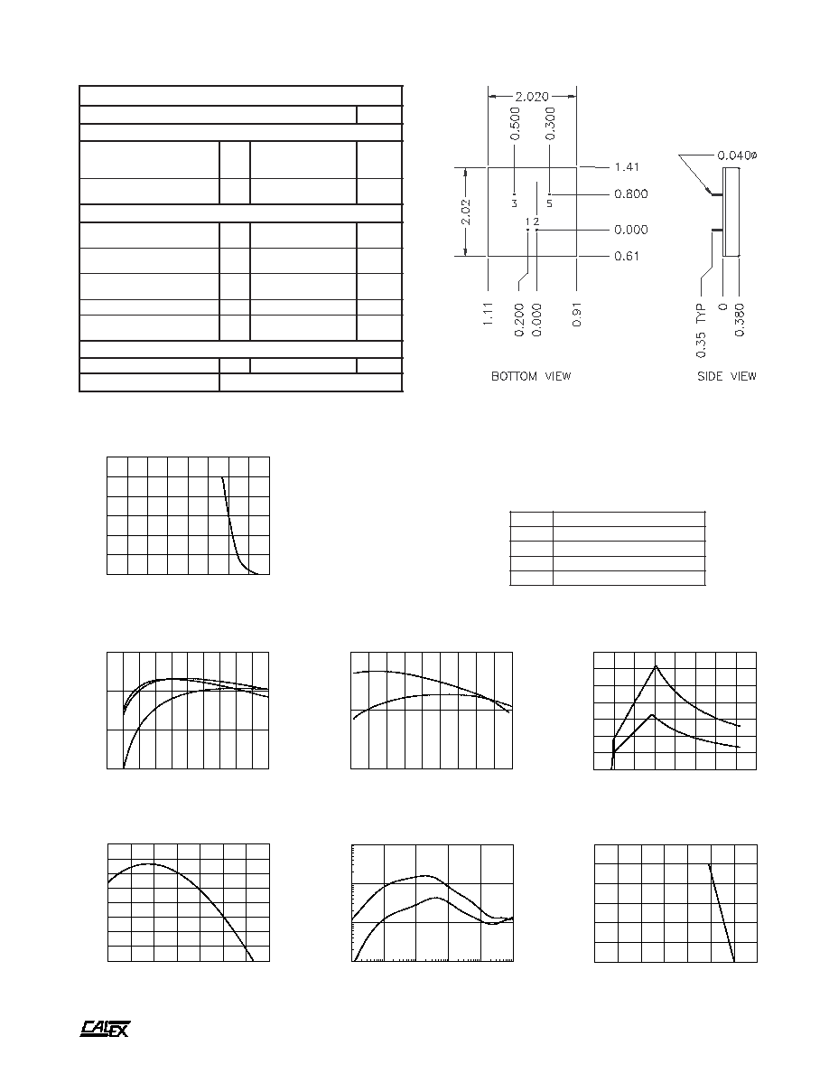
Mechanical tolerances unless otherwise noted:
X.XX dimensions: ±0.010 inches
X.XXX dimensions: ±0.005 inches
Seal around terminals is not hermetic. Do not immerse units in any
liquid.
-40
-20
0
20
40
60
80
100
CASE TEMPERATURE (Deg C)
-0.30
-0.25
-0.20
-0.15
-0.10
-0.05
-0.00
0.05
0.10
NORMALIZED OUTPUT (%)
OUTPUT VOLTAGE Vs CASE TEMPERATURE
10
100
1000
10000
100000
1000000
FREQUENCY (Hz)
.01
.1
1
10
OUTPUT IMPEDANCE (OHMS)
OUTPUT IMPEDANCE Vs. FREQUENCY
5 VOLT OUTPUT
15 VOLT OUTPUT
-40
-20
0
20
40
60
80
100
AMBIENT TEMPERATURE (Deg C)
0
20
40
60
80
100
120
OUTPUT POWER (%)
DERATING
INFINITE
HEAT
SINK
NO HEAT
SINK
SAFE
OPERATING
AREA
0
10
20
30
40
50
60
70
80
90
100
LOAD (%)
60
70
80
90
EFFICIENCY (%)
EFFICIENCY Vs. LOAD (12V OUTPUT)
LINE = 9VDC
LINE = 12VDC
LINE = 27VDC
9
11
13
15
17
19
21
23
25
27
LINE INPUT (VOLTS)
75
80
85
EFFICIENCY (%)
EFFICIENCY Vs. LINE INPUT (12V OUTPUT)
100% FULL LOAD
50% FULL LOAD
0
10
20
30
40
50
60
70
80
LINE INPUT (VOLTS)
0.00
0.05
0.10
0.15
0.20
0.25
0.30
0.35
INPUT CURRENT (AMPS)
48S5.1500, 48S12.625 & 48S15.500
INPUT CURRENT Vs LINE INPUT VOLTAGE
50%
FULL LOAD
100%
FULL LOAD
0
20
40
60
80
100
120
140
160
OUTPUT LOAD (%)
0
20
40
60
80
100
120
OUTPUT VOLTAGE (%)
OUTPUT VOLTAGE Vs. OUTPUT LOAD
Typical Performance (Tc=25∞C, Vin=Nom VDC, Rated Load).
*
s
n
o
i
t
a
c
i
f
i
c
e
p
S
l
a
r
e
n
e
G
s
l
e
d
o
M
l
l
A
s
t
i
n
U
)
4
(
n
o
i
t
a
l
o
s
I
e
g
a
t
l
o
V
n
w
o
d
k
a
e
r
B
t
u
p
t
u
O
-
t
u
p
n
I
e
g
a
k
a
e
L
A
µ
0
1
N
I
M
0
0
7
C
D
V
t
u
p
t
u
O
o
t
t
u
p
n
I
e
c
n
a
t
i
c
a
p
a
C
P
Y
T
0
4
3
F
p
l
a
t
n
e
m
n
o
r
i
v
n
E
e
g
n
a
R
g
n
i
t
a
r
e
p
O
e
s
a
C
g
n
i
t
a
r
e
D
o
N
N
I
M
X
A
M
5
2
-
5
8
C
∞
)
0
1
(
e
g
n
a
R
l
a
n
o
i
t
c
n
u
F
e
s
a
C
N
I
M
X
A
M
0
4
-
5
9
C
∞
e
g
n
a
R
e
g
a
r
o
t
S
N
I
M
X
A
M
5
5
-
5
0
1
C
∞
)
1
1
(
e
c
n
a
d
e
p
m
I
l
a
m
r
e
h
T
P
Y
T
0
1
t
t
a
W
/
C
∞
n
w
o
d
t
u
h
S
l
a
m
r
e
h
T
e
r
u
t
a
r
e
p
m
e
T
e
s
a
C
P
Y
T
0
0
1
C
∞
l
a
r
e
n
e
G
t
h
g
i
e
W
t
i
n
U
P
Y
T
7
.
1
z
o
s
t
i
K
g
n
i
t
n
u
o
M
6
S
M
&
5
1
S
M
A
5 to 7.5 Watt FW Single Series DC/DC Converters
Manufacturing Company, Inc. ∑ Concord, California 94520 ∑ Ph: 925/687-4411 or 800/542-3355 ∑ Fax: 925/687-3333 ∑ www.calex.com ∑ Email: sales@calex.com
4
STCO#970521-2,
eco# 041007-1
Description
These single output converters are designed for low noise,
telecommunications, industrial and instrument applications.
Their wide input range (2:1) makes them ideal for battery or
unregulated input applications.
These converters are state-of-the-art 120 KHz MOSFET
based designs that provide outstanding line and load regulation
with efficiencies approaching 85%.
The outputs are regulated by a high loop gain current mode
control method that provides linear regulator type performance
with a true, high efficiency switching DC/DC topology. The
large amount of loop gain also insures excellent input ripple
rejection and line transient response.
The FW Single converters are protected from output shorts
to common by a high speed, pulse-by-pulse, digital, current
limit circuit.
The input and output are overvoltage protected with transient
suppressor diodes. UL recognition under specification numbers
1459 and 1012 is currently pending.
Features
Improved Second Source Benefits:
Low noise outputs, 50 mV p-p maximum
Very low reflected ripple, 15 mA p-p maximum
Excellent regulation, 0.3% maximum
Improved line regulation, 0.1% maximum
Efficiencies to 84%
Reverse voltage protected input
Five Year Warranty
5 - 7.5 Watt FW Single Series Block Diagram
t
r
a
h
C
n
o
i
t
c
e
l
e
S
l
e
d
o
M
e
g
n
a
R
t
u
p
n
I
C
D
V
t
u
p
t
u
O
C
D
V
t
u
p
t
u
O
A
m
N
I
M
X
A
M
*
W
F
0
0
0
1
.
5
S
8
4
0
2
0
6
5
0
0
0
1
*
W
F
0
0
5
1
.
5
S
8
4
6
3
2
7
5
0
0
5
1
*
W
F
5
2
6
.
2
1
S
8
4
6
3
2
7
2
1
5
2
6
*
W
F
0
0
5
.
5
1
S
8
4
6
3
2
7
5
1
0
0
5
2
-
9
5
4
1
L
U
o
t
d
e
z
i
n
g
o
c
e
R
e
r
a
s
t
i
n
u
e
s
e
h
T
*
CURRENT
MODE
PWM
PROTECTION
DIODE
SIX-SIDED SHIELDED
COPPER CASE
BANDGAP REFERENCE
SHIELDED
ISOLATION TRANSFORMER
3
5
1
2
+ INPUT
- INPUT
+ OUTPUT
CMN
C1
C2
D1
t
u
p
t
u
O
1
C
2
C
1
D
5
F
µ
8
6
F
µ
8
7
V
8
.
6
2
1
F
µ
0
1
F
µ
0
2
V
5
1
5
1
F
µ
0
1
F
µ
0
2
V
8
1
A
5 to 7.5 Watt FW Single Series DC/DC Converters
Manufacturing Company, Inc. ∑ Concord, California 94520 ∑ Ph: 925/687-4411 or 800/542-3355 ∑ Fax: 925/687-3333 ∑ www.calex.com ∑ Email: sales@calex.com
5
STCO#970521-2,
eco# 041007-1
NOTES:
*
All parameters measured at Tc=25 ∞C, nominal input
voltage and full rated load unless otherwise noted. Refer to
the CALEX Application Notes for the definition of terms,
measurement circuits and other information.
(2)
Noise is measured per CALEX Application Notes. The output
noise is measured with a 0.1µF, 50V, ceramic capacitor connected
directly across the output pins. Measurement bandwidth is 0-20
MHz.
(3)
Determine the correct fuse size by calculating the maximum DC
current drain at low line input, maximum load and then adding 20
to 25% to get the desired fuse size. A slow blow type fuse
is recommended.
(4)
No minimum load required.
(5)
Short term stability is specified after a 30 minute warm-up at full
load, constant line and recording the drift over a 24 hour period.
(6)
The transient response is specified as the time required to settle
from a 50 to 75 % step load change (rise time of step = 2µ Sec)
to a 1% error band.
(7)
Dynamic response is the peak overshoot during a transient
as defined in note 6 above.
(8)
The input ripple rejection is specified for DC to 120 Hz ripple with
a modulation amplitude of 1% of Vin.
(9)
For module protection only, see also note 3.
(10) Case is tied to Pin 5, CMN.
(11) The functional temperature range is intended to give an additional
data point for use in evaluating this power supply. At the
low functional temperature the power supply will function with no
side effects, however sustained operation at the high functional
temperature will reduce expected operational life. The data
sheet specifications are not guaranteed over the functional
temperature range.
(12) The case thermal impedance is specified as the case temperature
rise over ambient per package watt dissipated.
(13) These products are UL Recognized for an input voltage range of
36 to 60 VDC.
*
s
r
e
t
e
m
a
r
a
P
t
u
p
n
I
l
e
d
o
M
W
F
0
0
0
1
.
5
S
8
4
W
F
0
0
5
1
.
5
S
8
4
)
3
1
(
W
F
5
2
6
.
2
1
S
8
4
)
3
1
(
W
F
0
0
5
.
5
1
S
8
4
)
3
1
(
s
t
i
n
U
e
g
n
a
R
e
g
a
t
l
o
V
N
I
M
X
A
M
0
.
0
2
0
.
0
6
0
.
6
3
0
.
2
7
0
.
6
3
0
.
2
7
0
.
6
3
0
.
2
7
C
D
V
w
b
z
H
M
0
2
-
0
,
)
2
(
e
l
p
p
i
R
d
e
t
c
e
l
f
e
R
P
Y
T
X
A
M
4
5
1
P
-
P
A
m
d
a
o
L
ll
u
F
t
n
e
r
r
u
C
t
u
p
n
I
d
a
o
L
o
N
P
Y
T
P
Y
T
9
3
1
5
5
9
1
3
0
9
1
4
5
8
1
4
A
m
y
c
n
e
i
c
i
f
f
E
P
Y
T
5
7
0
8
2
8
5
8
%
y
c
n
e
u
q
e
r
F
g
n
i
h
c
t
i
w
S
P
Y
T
0
2
1
z
H
k
e
g
a
t
l
o
v
r
e
v
O
t
u
p
n
I
m
u
m
i
x
a
M
e
g
a
m
a
D
o
N
s
m
0
0
1
X
A
M
0
8
C
D
V
r
o
r
r
E
t
u
p
t
u
O
%
1
,
e
m
i
T
n
o
-
n
r
u
T
P
Y
T
0
1
s
m
e
s
u
F
d
e
d
n
e
m
m
o
c
e
R
)
3
(
y
t
i
r
a
l
o
P
e
s
r
e
v
e
R
0
7
C
D
V
*
s
r
e
t
e
m
a
r
a
P
t
u
p
t
u
O
l
e
d
o
M
W
F
0
0
0
1
.
5
S
8
4
W
F
0
0
5
1
.
5
S
8
4
W
F
5
2
6
.
2
1
S
8
4
W
F
0
0
5
.
5
1
S
8
4
s
t
i
n
U
e
g
a
t
l
o
V
t
u
p
t
u
O
5
5
2
1
5
1
C
D
V
)
4
(
t
n
e
r
r
u
C
d
e
t
a
R
N
I
M
X
A
M
0
.
0
0
0
0
1
0
.
0
0
0
5
1
0
.
0
5
2
6
0
.
0
0
0
5
A
m
e
g
n
a
R
e
g
a
t
l
o
V
d
a
o
L
%
0
0
1
N
I
M
P
Y
T
X
A
M
0
5
9
.
4
0
0
0
.
5
0
5
0
.
5
0
5
9
.
4
0
0
0
.
5
0
5
0
.
5
0
0
9
.
1
1
0
0
0
.
2
1
0
0
1
.
2
1
0
0
9
.
4
1
0
0
0
.
5
1
0
0
1
.
5
1
C
D
V
%
0
0
1
-
0
n
o
i
t
a
l
u
g
e
R
d
a
o
L
P
Y
T
X
A
M
1
.
0
3
.
0
5
0
.
0
1
.
0
%
n
o
i
t
a
l
u
g
e
R
e
n
i
L
C
D
V
x
a
M
-
n
i
M
=
n
i
V
P
Y
T
X
A
M
1
0
.
0
1
.
0
%
)
5
(
y
t
il
i
b
a
t
S
m
r
e
T
t
r
o
h
S
P
Y
T
5
0
.
0
5
0
.
0
2
0
.
0
2
0
.
0
s
r
H
4
2
/
%
y
t
il
i
b
a
t
S
m
r
e
T
g
n
o
L
P
Y
T
2
.
0
<
s
r
H
k
/
%
)
6
(
e
s
n
o
p
s
e
R
t
n
e
i
s
n
a
r
T
P
Y
T
0
5
5
2
1
0
0
2
0
5
1
s
µ
)
7
(
e
s
n
o
p
s
e
R
c
i
m
a
n
y
D
P
Y
T
0
0
1
0
8
1
0
0
2
0
7
1
k
a
e
p
V
m
)
8
(
n
o
i
t
c
e
j
e
R
e
l
p
p
i
R
t
u
p
n
I
P
Y
T
8
3
B
d
)
2
(
w
b
z
H
M
0
2
-
0
,
e
s
i
o
N
r
o
t
i
c
a
p
a
C
l
a
n
r
e
t
x
E
F
µ
1
.
0
h
t
i
w
r
o
t
i
c
a
p
a
C
l
a
n
r
e
t
x
E
o
n
h
t
i
w
P
Y
T
X
A
M
P
Y
T
X
A
M
0
1
0
5
0
4
0
0
1
P
-
P
V
m
t
n
e
i
c
i
f
f
e
o
C
e
r
u
t
a
r
e
p
m
e
T
P
Y
T
X
A
M
0
5
0
5
1
C
∞
/
m
p
p
)
9
(
p
m
a
l
C
e
g
a
t
l
o
v
r
e
v
O
P
Y
T
8
.
6
8
.
6
5
1
8
1
C
D
V
o
t
n
o
i
t
c
e
t
o
r
P
t
i
u
c
r
i
C
t
r
o
h
S
s
t
u
p
t
u
O
ll
a
r
o
f
n
o
m
m
o
C
l
a
m
r
e
h
t
d
n
a
g
n
i
t
i
m
il
t
n
e
r
r
u
c
h
t
i
w
n
o
i
t
c
e
t
o
r
p
s
u
o
n
i
t
n
o
c
s
r
u
o
h
8
f
o
m
u
m
i
n
i
m
s
e
d
i
v
o
r
P
s
e
u
q
i
n
h
c
e
t
d
a
o
l
r
e
v
o