 | –≠–ª–µ–∫—Ç—Ä–æ–Ω–Ω—ã–π –∫–æ–º–ø–æ–Ω–µ–Ω—Ç: 48T5.12XC | –°–∫–∞—á–∞—Ç—å:  PDF PDF  ZIP ZIP |

A
25 to 30 Watt XC Triple Series DC/DC Converters
2401 Stanwell Drive ∑ Concord, California 94520 ∑ Ph: 925/687-4411 or 800/542-3355 ∑ Fax: 925/687-3333 ∑ www.calex.com ∑ Email: sales@calex.com
1
3/2001, eco# 041007-1
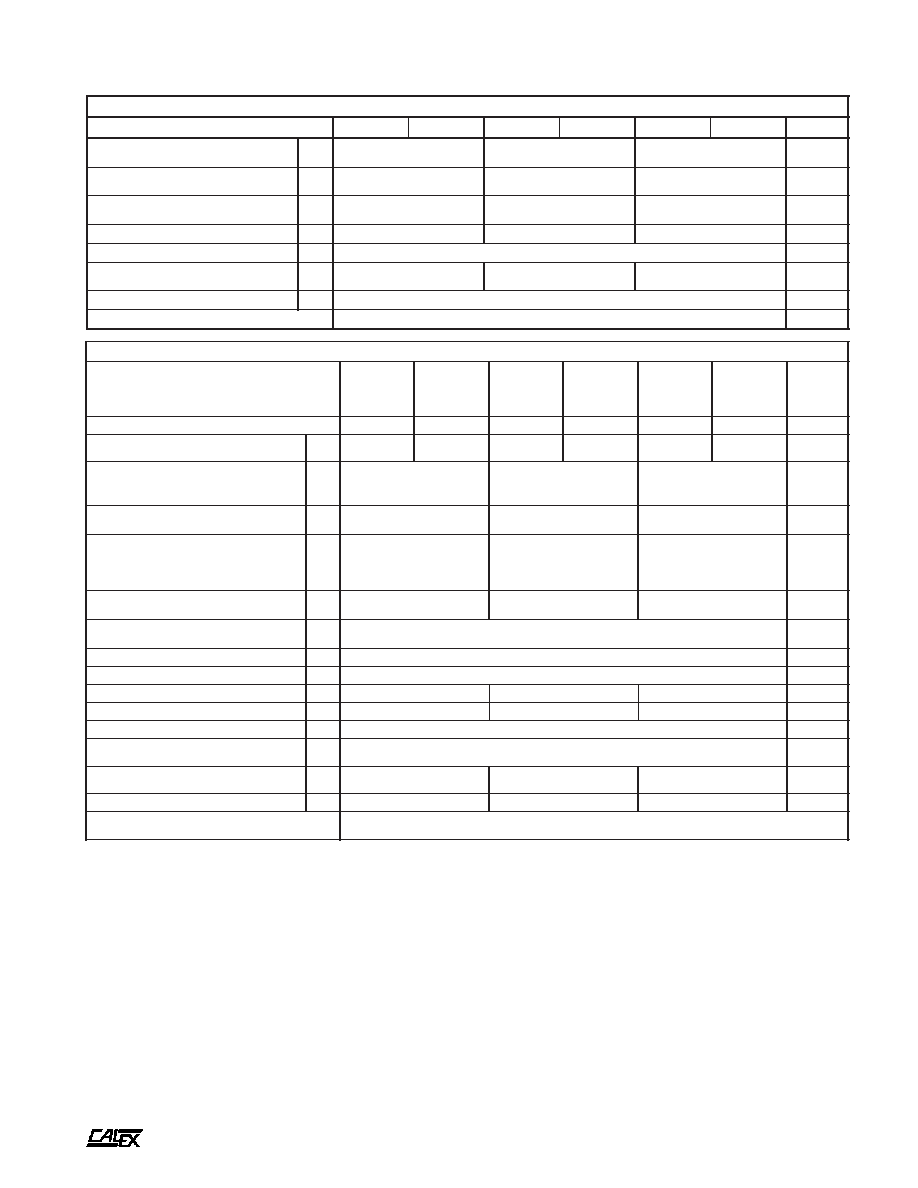
ANTI-PHASE
DUAL PWM
CONTROLLER
DIFFERENTIAL
MODE
INPUT
FILTER
SHIELDED
ISOLATION TRANSFORMERS
THERMAL SHUTDOWN
SINGLE SECTION
ISOLATION BARRIER
DUAL SECTION
SHIELDED, LOW THERMAL GRADIENT COPPER CASE
48T MODELS
ONLY
12T AND 24T
MODELS
+ INPUT
- INPUT
ON/OFF
1
2
8
6
7
9
3
4
5
+ 5
+ 5 CMN
+ 5 TRIM
+ 12/15
± CMN
- 12/15
Features
Single and Dual Output Sections Isolated
from each Other and Independently Regulated
Overall Output Accuracy up to 10:1 Better than
Competitive Products
Standby Current Less than 0.5 mA for Low Power
Pulsed Battery Operation
Fully Filtered and Specified; Very Low Noise Inputs
and Outputs
PCB Mounting with Optional Heat Sink and Chassis
Mounting Kit
Industrial Operating Temperature Range Standard,
-40 to 85∞C
Five Year Warranty
Description
The 25-30 Watt Triple Series opens up new application areas
in high efficiency DC/DC conversion. The unique dual control
loop output design allows for independent regulation of both
the single and dual outputs. This increases the total output
accuracy by up to 10:1 over competitive designs. The design
also eliminates cross regulation from the +5 section to the
dual outputs. The 25-30 Watt Triple Series runs at 80-85%
efficiency.
25-30 Watt Triple Series Block Diagram
t
r
a
h
C
n
o
i
t
c
e
l
e
S
l
e
d
o
M
e
g
n
a
R
t
u
p
n
I
C
D
V
s
t
u
p
t
u
O
C
D
V
s
t
u
p
t
u
O
A
m
n
i
M
x
a
M
C
X
2
1
.
5
T
2
1
0
.
0
1
0
.
0
2
2
1
±
,
5
0
0
5
±
,
0
0
5
2
C
X
5
1
.
5
T
2
1
0
.
0
1
0
.
0
2
5
1
±
,
5
0
0
4
±
,
0
0
5
2
C
X
2
1
.
5
T
4
2
0
.
8
1
0
.
6
3
2
1
±
,
5
5
2
6
±
,
0
0
0
3
C
X
5
1
.
5
T
4
2
0
.
8
1
0
.
6
3
5
1
±
,
5
0
0
5
±
,
0
0
0
3
C
X
2
1
.
5
T
8
4
0
.
6
3
0
.
2
7
2
1
±
,
5
5
2
6
±
,
0
0
0
3
C
X
5
1
.
5
T
8
4
0
.
6
3
0
.
2
7
5
1
±
,
5
0
0
5
±
,
0
0
0
3
A
25 to 30 Watt XC Triple Series DC/DC Converters
2401 Stanwell Drive ∑ Concord, California 94520 ∑ Ph: 925/687-4411 or 800/542-3355 ∑ Fax: 925/687-3333 ∑ www.calex.com ∑ Email: sales@calex.com
2
3/2001, eco# 041007-1
change in either output as the loads on both outputs are changed
from minimum load to maximum load at the same time.
(6)
Cross regulation is defined as the change in one output when the
other output is changed from minimum to maximum load.
(7)
Short term stability is specified after a 30 minute warmup at full
load, constant line, load and ambient conditions.
(8)
Transient response is defined as the time for the output to settle
from a 25 to 75 % step load change to a 1% error band (rise time
of step = 2µ Sec).
(9)
Dynamic response is defined as the peak overshoot during a
transient as defined in note 8 above.
(10) The input ripple rejection is specified for DC to 120 Hz ripple with
a modulation amplitude of 1% of Vin.
(11) For module protection only, see also note 3.
(12) The ON/OFF pin is Open Collector TTL, CMOS, and relay
compatible. The input to this pin is referenced to the -input.
NOTES
*
All parameters measured at Tc = 25∞C, nominal input voltage
and full rated load unless otherwise noted. Refer to the
CALEX Application Notes for the definition of terms,
measurement circuits and other information.
(2)
Noise is measured per CALEX Application Notes found in the
CALEX Power Conversion Design Guide and Catalog.
Measurement bandwidth is 0 - 20 MHz. See the applications
section of this note for more information.
(3)
Determine the correct fuse size by calculating the maximum DC
current drain at low line input, maximum load and then adding 20
to 25% to get the desired fuse size. A slow blow type fuse is
recommended.
(4)
Minimum load is required for proper regulation only. No module
damage is sustained if run less than minimum load. Regulation
of the dual output degrades with substantial load unbalance.
(5)
The dual section load regulation is defined as the voltage
*
s
r
e
t
e
m
a
r
a
P
t
u
p
n
I
l
e
d
o
M
C
X
2
1
.
5
T
2
1
C
X
5
1
.
5
T
2
1
C
X
2
1
.
5
T
4
2
C
X
5
1
.
5
T
4
2
C
X
2
1
.
5
T
8
4
C
X
5
1
.
5
T
8
4
s
t
i
n
U
e
g
n
a
R
e
g
a
t
l
o
V
N
I
M
X
A
M
0
.
0
1
0
.
0
2
0
.
8
1
0
.
6
3
0
.
6
3
0
.
2
7
C
D
V
w
b
z
H
M
0
2
-
0
,
)
2
(
e
l
p
p
i
R
d
e
t
c
e
l
f
e
R
P
Y
T
X
A
M
0
5
3
0
0
5
0
5
1
0
0
3
0
5
1
0
5
3
P
-
P
A
m
d
a
o
L
ll
u
F
t
n
e
r
r
u
C
t
u
p
n
I
d
a
o
L
o
N
P
Y
T
P
Y
T
0
5
5
2
0
3
5
6
4
1
0
2
5
3
7
5
1
A
m
y
c
n
e
i
c
i
f
f
E
P
Y
T
0
8
5
8
5
8
%
y
c
n
e
u
q
e
r
F
g
n
i
h
c
t
i
w
S
P
Y
T
0
2
1
z
H
k
,
e
g
a
t
l
o
v
r
e
v
O
t
u
p
n
I
m
u
m
i
x
a
M
e
g
a
m
a
D
o
N
s
m
0
0
1
X
A
M
5
2
5
4
5
8
C
D
V
r
o
r
r
E
t
u
p
t
u
O
%
1
,
e
m
i
T
n
o
-
n
r
u
T
P
Y
T
5
3
s
m
e
s
u
F
d
e
d
n
e
m
m
o
c
e
R
)
3
(
s
p
m
A
*
s
r
e
t
e
m
a
r
a
P
t
u
p
t
u
O
l
e
d
o
M
C
X
2
1
.
5
T
2
1
C
X
5
1
.
5
T
2
1
C
X
2
1
.
5
T
4
2
C
X
5
1
.
5
T
4
2
C
X
2
1
.
5
T
8
4
C
X
5
1
.
5
T
8
4
C
X
2
1
.
5
T
2
1
C
X
2
1
.
5
T
4
2
C
X
2
1
.
5
T
8
4
C
X
5
1
.
5
T
2
1
C
X
5
1
.
5
T
4
2
C
X
5
1
.
5
T
8
4
s
t
i
n
U
e
g
a
t
l
o
V
t
u
p
t
u
O
5
+
5
+
2
1
±
2
1
±
5
1
±
5
1
±
C
D
V
)
4
(
t
n
e
r
r
u
C
d
e
t
a
R
N
I
M
X
A
M
0
0
0
5
2
0
0
0
0
3
0
6
1
0
0
5
0
6
1
5
2
6
5
2
1
0
0
4
5
2
1
0
0
5
A
m
e
g
n
a
R
e
g
a
t
l
o
V
d
a
o
L
%
0
0
1
N
I
M
P
Y
T
X
A
M
0
5
9
.
4
0
0
0
.
5
0
5
0
.
5
5
2
9
.
1
1
0
0
0
.
2
1
5
7
0
.
2
1
5
2
9
.
4
1
0
0
0
.
5
1
5
7
0
.
5
1
C
D
V
e
c
n
a
l
a
B
t
u
p
t
u
O
)
d
a
o
L
ll
u
F
,
t
u
p
t
u
O
s
u
n
i
M
o
t
s
u
l
P
(
P
Y
T
X
A
M
A
/
N
A
/
N
5
.
0
7
.
0
5
.
0
7
.
0
%
d
a
o
L
%
0
0
1
-
5
2
n
o
i
t
a
l
u
g
e
R
d
a
o
L
)
5
(
%
0
0
1
-
0
P
Y
T
X
A
M
P
Y
T
X
A
M
4
.
0
7
.
0
5
.
0
5
7
.
0
5
0
.
0
1
.
0
1
.
0
2
.
0
5
0
.
0
1
.
0
1
.
0
2
.
0
%
)
6
(
n
o
i
t
a
l
u
g
e
r
s
s
o
r
C
P
Y
T
X
A
M
A
/
N
A
/
N
6
.
0
8
.
0
5
.
0
5
7
.
0
%
n
o
i
t
a
l
u
g
e
R
e
n
i
L
C
D
V
x
a
M
-
n
i
M
=
n
i
V
P
Y
T
X
A
M
0
.
0
1
.
0
%
)
7
(
y
t
il
i
b
a
t
S
m
r
e
T
t
r
o
h
S
P
Y
T
2
0
.
0
%
y
t
il
i
b
a
t
S
m
r
e
T
g
n
o
L
P
Y
T
1
.
0
s
r
H
k
/
%
)
8
(
e
s
n
o
p
s
e
R
t
n
e
i
s
n
a
r
T
P
Y
T
0
0
1
0
0
2
0
0
2
s
µ
)
9
(
e
s
n
o
p
s
e
R
c
i
m
a
n
y
D
P
Y
T
0
7
2
0
5
2
0
0
2
k
a
e
p
V
m
)
0
1
(
n
o
i
t
c
e
j
e
R
e
l
p
p
i
R
t
u
p
n
I
P
Y
T
0
7
>
B
d
)
2
(
w
b
z
H
M
0
2
-
0
,
e
s
i
o
N
P
Y
T
X
A
M
0
3
5
6
P
-
P
V
m
t
n
e
i
c
i
f
f
e
o
C
e
r
u
t
a
r
e
p
m
e
T
P
Y
T
X
A
M
0
5
0
0
1
0
5
0
0
2
0
5
0
0
2
C
∞
/
m
p
p
)
1
1
(
p
m
a
l
C
e
g
a
t
l
o
v
r
e
v
O
P
Y
T
8
.
6
5
1
8
1
C
D
V
o
t
n
o
i
t
c
e
t
o
r
P
t
i
u
c
r
i
C
t
r
o
h
S
s
t
u
p
t
u
O
ll
a
r
o
f
n
o
m
m
o
C
d
n
a
g
n
i
t
i
m
il
t
n
e
r
r
u
c
h
t
i
w
n
o
i
t
c
e
t
o
r
p
s
u
o
u
n
i
t
n
o
c
s
r
u
o
h
8
f
o
m
u
m
i
n
i
m
s
e
d
i
v
o
r
P
s
e
u
q
i
n
h
c
e
t
d
a
o
l
r
e
v
o
l
a
m
r
e
h
t

A
25 to 30 Watt XC Triple Series DC/DC Converters
2401 Stanwell Drive ∑ Concord, California 94520 ∑ Ph: 925/687-4411 or 800/542-3355 ∑ Fax: 925/687-3333 ∑ www.calex.com ∑ Email: sales@calex.com
3
3/2001, eco# 041007-1
Heat Sink Option
The 25-30 Watt Triple can be ordered with a "-I" configuration
which provides a case with 3 by M3 inserts located on the top
surface of the case for attaching a heat sink. When an "-HS"
is ordered CALEX will ship the converter with a heat sink
attached. The CALEX HS heat sink was specially developed
for this model and can reduce the case temperature rise to
below 3.3∞C per watt with natural convection and less with
moving air. One heat sink is needed for each 25-30 Watt
Triple ordered.
Customer installed heat sinks may also be used. It is
recommended that only liquid heat sink compound be used on
the heat sink interface. Avoid the so called "Dry" pad heat sink
materials. In our experience these materials are actually
worse than using no compound at all.
Mechanical tolerances unless otherwise noted:
X.XX dimensions: ±0.020 inches
X.XXX dimensions: ±0.005 inches
Seal around terminals is not hermetic. Do not immerse units in any
liquid.
BOTTOM VIEW
SIDE VIEW
(13) The functional temperature range is intended to give an additional
data point for use in evaluating this power supply. At the low
functional temperature the power supply will function with no
side effects, however, sustained operation at the high functional
temperature will reduce expected operational life. The data
sheet specifications are not guaranteed over the functional
temperature range.
(14) Specifications subject to change without notice.
(15) Water Washability - Calex DC/DC converters are designed to
withstand most solder/wash processes. Careful attention should
be used when assessing the applicability in your specific
manufacturing process. Converters are not hermetically sealed.
Chassis Mounting Kit - MS12
The MS12 chassis mounting kit allows for direct wire connection
to the 25-30 Watt Triple Series. The mounting kit includes two
barrier strips for wire attachment, an input fuse and an output
trim pot for trimming the +5 volt output. Provisions are also
made for additional output bypassing and grounding.
If the MS12 is ordered at the same time as a 25-30 Watt
Triple the mounting kit will be shipped with the correct fuse
size.
The MS12 may be conveniently attached to a chassis by
using the 4 - 0.156 inch diameter mounting holes provided at
each corner.
Although the MS12 comes with solderless sockets for the
25-30 Watt Triple, it is recommended that the converter be
soldered to the mounting kit for improved reliability under
severe environmental or vibration conditions.
*
s
n
o
i
t
a
c
i
f
i
c
e
p
S
l
a
r
e
n
e
G
s
l
e
d
o
M
l
l
A
s
t
i
n
U
)
2
1
(
n
o
i
t
c
n
u
F
F
F
O
/
N
O
l
e
v
e
L
c
i
g
o
L
N
O
n
e
p
O
n
i
P
e
v
a
e
L
r
o
N
I
M
4
.
2
C
D
V
l
e
v
e
L
c
i
g
o
L
F
F
O
X
A
M
5
.
1
C
D
V
e
c
n
a
t
s
i
s
e
R
t
u
p
n
I
P
Y
T
2
s
m
h
o
k
,
t
n
e
r
r
u
C
e
l
d
I
r
e
t
r
e
v
n
o
C
w
o
L
n
i
P
n
w
o
D
t
u
h
S
P
Y
T
2
1
A
m
n
o
i
t
a
l
o
s
I
e
g
a
t
l
o
V
n
o
i
t
a
l
o
s
I
t
u
p
t
u
O
r
e
h
t
i
E
o
t
t
u
p
n
I
t
u
p
t
u
O
l
a
u
D
o
t
e
l
g
n
i
S
e
g
a
k
a
e
L
A
µ
0
1
N
I
M
N
I
M
4
4
5
1
0
0
5
C
D
V
t
u
p
t
u
O
o
t
t
u
p
n
I
e
c
n
a
t
i
c
a
p
a
C
t
u
p
t
u
O
e
l
g
n
i
S
o
t
t
u
p
n
I
t
u
p
t
u
O
l
a
u
D
o
t
t
u
p
n
I
t
u
p
t
u
O
l
a
u
D
o
t
e
l
g
n
i
S
P
Y
T
P
Y
T
P
Y
T
5
9
0
9
5
4
F
p
l
a
t
n
e
m
n
o
r
i
v
n
E
e
g
n
a
R
g
n
i
t
a
r
e
p
O
e
s
a
C
g
n
i
t
a
r
e
D
o
N
N
I
M
X
A
M
0
4
-
5
8
C
∞
)
3
1
(
e
g
n
a
R
l
a
n
o
i
t
n
u
F
e
s
a
C
N
I
M
X
A
M
0
4
-
0
9
C
∞
e
g
n
a
R
e
g
a
r
o
t
S
N
I
M
X
A
M
5
5
-
5
0
1
C
∞
e
c
n
a
d
e
p
m
I
l
a
m
r
e
h
T
n
o
i
s
r
e
V
t
n
u
o
M
n
i
P
P
Y
T
4
.
4
t
t
a
W
/
C
∞
n
w
o
d
t
u
h
S
l
a
m
r
e
h
T
e
r
u
t
a
r
e
p
m
e
T
e
s
a
C
P
Y
T
0
0
1
C
∞
l
a
r
e
n
e
G
t
h
g
i
e
W
t
i
n
U
2
.
6
.
z
o
t
i
K
g
n
i
t
n
u
o
M
2
1
S
M
s
l
a
v
o
r
p
A
y
c
n
e
g
A
9
5
4
1
L
U
n
i
P
n
o
i
t
c
n
u
F
n
i
P
n
o
i
t
c
n
u
F
1
T
U
P
N
I
+
6
V
5
+
2
T
U
P
N
I
-
7
N
M
C
3
V
5
1
/
2
1
+
8
F
F
O
/
N
O
4
N
M
C
9
M
I
R
T
V
5
+
5
V
5
1
/
2
1
-
A
25 to 30 Watt XC Triple Series DC/DC Converters
2401 Stanwell Drive ∑ Concord, California 94520 ∑ Ph: 925/687-4411 or 800/542-3355 ∑ Fax: 925/687-3333 ∑ www.calex.com ∑ Email: sales@calex.com
4
3/2001, eco# 041007-1
TRIM DOWN
TRIM UP
+ 5 LOAD
10K TRIMPOT
6
9
7
+ 5
+ 5 TRIM
+ 5 CMN
1
2
8
6
7
9
3
4
5
+ INPUT
- INPUT
ON/OFF
+ 5 LOAD
+ 5 TRIM
+ LOAD
- LOAD
+ 5
+ 5 CMN
+ 5 TRIM
+ 12/15
± CMN
- 12/15
ON/OFF
- INPUT
+ INPUT
FUSE
Application Information
The dual control loops are locked together in time by a
proprietary "Anti-Phase Dual PWM Controller" subassembly.
The synchronization reduces beat frequency problems that
occur when two switching supplies run at slightly different
frequencies. The "Anti-Phase" operation also evens out the
current pulses on the input bulk capacitor allowing for
conservative derating and hence longer life.
The dual loop design allows both the single and dual
outputs to be fully isolated from each other. This helps the
system design by allowing the common analog and digital
ground point to be elsewhere in the system. The dual outputs
can also be used as single ended 24 or 30 volt outputs.
The 25-30 Watt Triple Series is also mindful of battery
operation for industrial/medical control and remote data
collection. The remote ON/OFF control pin places the converter
in a very low power mode that draws only 0.5 mA maximum
from the input source. This is at least a 10:1 improvement over
industry standard specifications of 5 to 30 mA standby current
drain.
These converters achieve an output noise of 30 mV peak
to peak typical and are fully specified and tested to a maximum
specification of 65 mV peak to peak over a wide bandwidth of
0-20 MHz. Input filtering reduces reflected ripple noise and is
similarly low and also fully specified for typical and maximum
values (exact value depends on input voltage range).
All inputs and outputs are protected from transient
overvoltage conditions by 500 watt transient overvoltage
suppressors. Full overload protection is provided by
independent pulse-by-pulse current limiting and
overtemperature shutdown. These protection features assure
you that our 25-30 Watt Triple will provide zero failure rate
operation.
Six-sided shielding is standard along with specified
operation over the full industrial temperature range of -40∞ to
+85∞C.
The 25-30 Watt Triple Series, like all CALEX converters,
carries the full 5 year CALEX no hassle warranty. We can offer
a five year warranty where others can't because with CALEX
it's rarely needed.
General Operation
Figure 1 shows the recommended connections for the 25-30
Watt Triple DC/DC converter. A fuse is recommended to
protect the input circuit and should not be omitted. The fuse
serves two purposes:
1)
It prevents unlimited current from flowing in the case of
a catastrophic system failure.
2)
UL regulations for telecom equipment require the use of
a fuse.
Figure 1.
Standard connections for the 25-30 Watt Triple. The ON/OFF and
Trim pins can be left floating if they are not used. The input fuse
should not be omitted.
The ON/OFF and +5 trim pins may be left floating if they are
not used. No external capacitance on either the input or
outputs is required for normal use which can, in fact, degrade
the converter's operation. See our application note
"Understanding Power Supply Output Impedance for Optimum
Decoupling" for more information. The usual 0.1 to 0.01µF
bypasses may be used around your PCB as required for local
bypassing without harm. Extremely low ESR capacitors ( <0.2
ohms) should not be used at the input. This will cause peaking
of the input filters' transfer function and actually degrade the
filters' performance.
Single Output
The single output is independently regulated and isolated
from the dual outputs and can be operated independently or
with a common ground with the dual output.
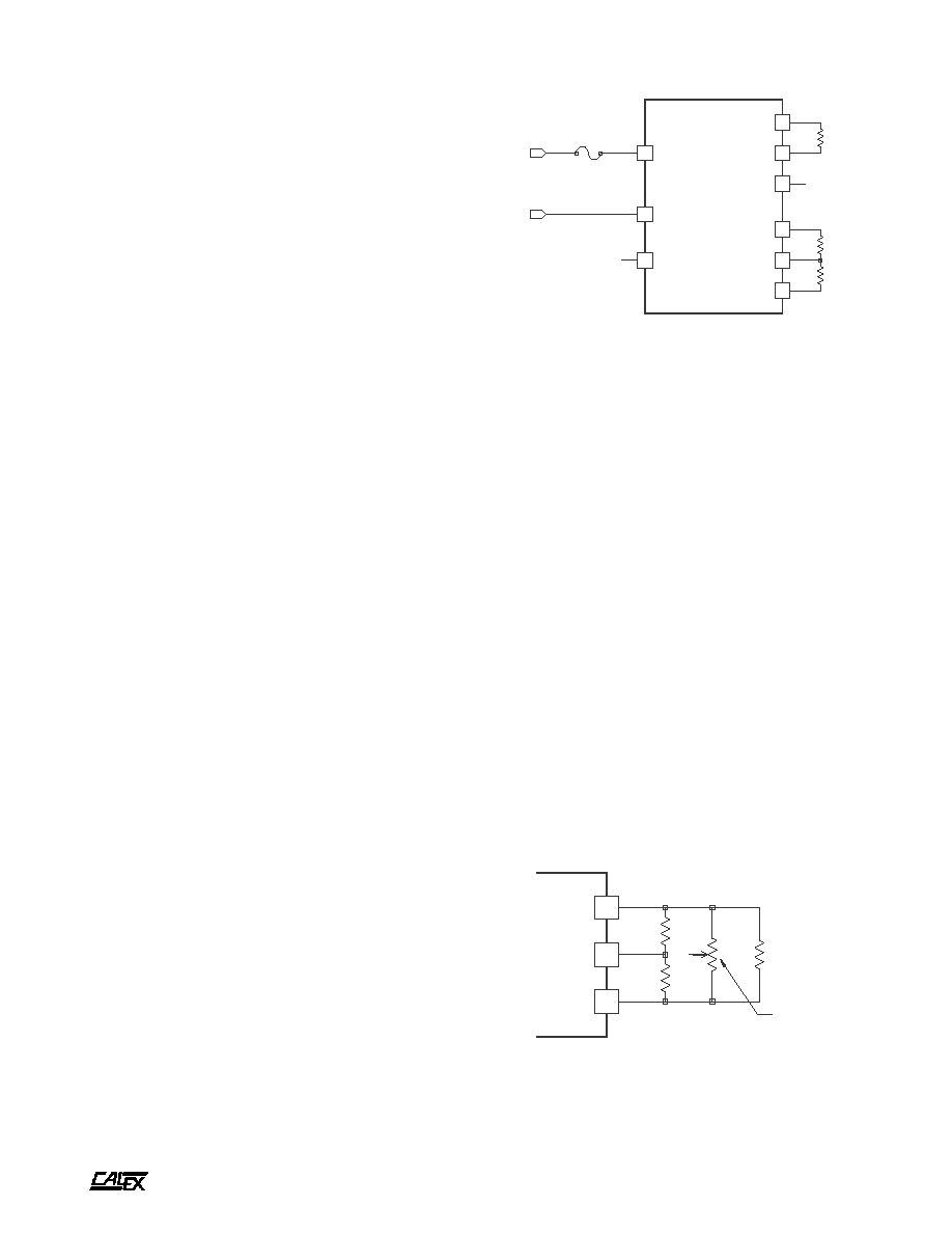
The +5 TRIM pin may be used to adjust the +5 volt output
by up to ±5 % from the nominal factory setting of +5.000 volts.
The trim may be used to adjust for system wiring voltage drops
or to adjust the +5 output up to 5.2 volts for ECL applications.
Since the 5 volt output is completely isolated from the dual
section the output can be grounded to generate -5.2 volts or
+5.2 volts. Figure 2 shows the proper connections for the trim
pin.
Figure 2.
The 5 volt output can be trimmed by using either a trimpot or fixed
resistors. If fixed resistors are used their values may range from
zero to infinite ohms the trimpot should be 10K ohms nominal.

A
25 to 30 Watt XC Triple Series DC/DC Converters
2401 Stanwell Drive ∑ Concord, California 94520 ∑ Ph: 925/687-4411 or 800/542-3355 ∑ Fax: 925/687-3333 ∑ www.calex.com ∑ Email: sales@calex.com
5
3/2001, eco# 041007-1
3
4
5
+ 12/15
± CMN
- 12/15
+ LOAD
- LOAD
24 or 30V
LOAD
+ INPUT
ON/OFF
- INPUT
1
8
2
100K
15V
100 W
REMOTE
+ 5 VOLT
LOAD
6
9
7
+ 5
+ 5 TRIM
+ 5 CMN
R1
R3
R4
Q1
C1
IC1
R5
R2
Figure 3.
This simple circuit allows for remote sensing with the 5 volt output.
The circuit can correct for up to 0.25 volts of total drop in the power
leads. At 3 amps of output this is approximately 0.08 ohms of line
resistance. A trimpot may be added to R5 to allow for exact
adjustment of the 5 volt output.
Figure 3 shows how to implement remote sense with the
trim pin and a TL431 adjustable voltage reference. This circuit
allows automatic correction of the output voltage up to 0.25
volts total.
Dual Output
The dual output is independently regulated and isolated from
the single output and can be operated separately or with a
common ground with the single output. The dual outputs can
also be connected for single-ended load applications of either
24 or 30 volts as shown in Figure 4. This configuration allows
for full output current operation up to the full 25 or 30 watt
rating.
Figure 4.
The dual output may be used either as a dual polarity or single-
ended source. If the output is used as a single-ended source, pin 4
should be left unconnected.
Grounding
The +5 and ± dual sections are floating independently from
each other. They may be operated this way or with a common
ground.
If the single and dual sections are connected either directly
at the converter or at some remote location it is suggested that
1 µF, 35 volt Tantalum capacitor bypasses be used directly at
the converter output pins. These capacitors prevent any
common mode switching currents from showing up on the
converter's outputs as normal mode output noise.
Do not use the lowest ESR, biggest value capacitor that
you can find! This can only lead to reduced system performance
or oscillation.
See our application note "Understanding Power Supply
Output Impedance for Optimum Decoupling" in the CALEX
Power Conversion Design Guide and Catalog for more
information.
Figure 5.
The simplified schematic of the ON/OFF pin shows a 100K resistor
connected between the +Input and the ON/OFF pin. The maximum
open circuit voltage is clamped by the 15 volt zener diode. The 100
ohm resistor prevents large ground currents from flowing out the
ON/OFF pin instead of the -Input pin during power up transients.
Case Grounding
The case serves not only as a heat sink but also as an EMI
shield. The case/header shield is tied to the +Input pin for the
48T models. The 12T and 24T models have the case tied to
the -Input pin. These connections are shown on the 25-30
Watt Triple block diagram.
For all models the case is floating from the output sections.
Remote ON/OFF Pin Operation
The remote ON/OFF pin may be left floating if this function is
not used. The equivalent input circuit for the ON/OFF pin is
shown in Figure 5. The best way to drive this pin is with an
open collector/drain or relay contact. See our application note
titled "Understanding the Remote ON/OFF Function" for more
information about using the remote ON/OFF pin.
When the ON/OFF pin is pulled low with respect to the -
Input, the converter is placed in a low power drain state. This
low power state typically draws less than 200 mA from the
input source. When the ON/OFF pin is released the converter
powers up in typically 35 mSec. The ON/OFF pin turns the
converter off while keeping the input bulk capacitor fully
charged. This prevents the large inrush current spike that
occurs when the +Input pin is opened and closed.
Temperature Derating / Mounting Options
The XC Triple Series can operate up to 85∞C case temperature
without derating. Case temperature may be roughly calculated
from ambient by knowing that the XC Triples' case temperature
rise is 4.4∞C per package watt dissipated. For example, if the
converter was functioning at an output of 30 Watts, at what
ambient could it expect to run with no moving air and no
additional heatsinks?
t
s
i
L
s
t
r
a
P
1
C
c
i
m
a
r
e
C
,
V
0
5
,
F
µ
1
.
0
4
R
%
1
,
K
9
9
.
4
1
R
%
5
,
m
h
o
0
7
4
5
R
%
1
,
K
9
9
.
4
2
R
%
5
,
K
0
.
1
1
Q
6
0
9
3
N
2
3
R
%
5
,
K
4
.
2
I 1
C
1
3
4
L
T

A
25 to 30 Watt XC Triple Series DC/DC Converters
2401 Stanwell Drive ∑ Concord, California 94520 ∑ Ph: 925/687-4411 or 800/542-3355 ∑ Fax: 925/687-3333 ∑ www.calex.com ∑ Email: sales@calex.com
6
3/2001, eco# 041007-1
Efficiency is approximately 85%, this leads to an input
power of 35 watts. The case temperature rise would be 5 watts
x 4.4 = 22∞C. This number is subtracted from the maximum
case temperature of 85∞C to get 63∞C.
This is a rough approximation of the maximum ambient
temperature. Because of the difficulty of defining ambient
temperature and the possibility that the loads' dissipation may
actually increase the local ambient temperature significantly,
these calculations should be verified by actual measurement
before committing to a production design.
Typical Performance (Tc=25∞C, Vin=Nom VDC, Rated Load).
0
10
20
30
40
50
60
70
80
90
100
LOAD (%)
60
65
70
75
80
85
EFFICIENCY (%)
12 VOLT EFFICIENCY Vs. LOAD
LINE = 10VDC
LINE = 12VDC
LINE = 20VDC
0
2
4
6
8
10
12
14
16
18
20
LINE INPUT (VOLTS)
0.0
0.5
1.0
1.5
2.0
2.5
3.0
3.5
INPUT CURRENT (AMPS)
12 VOLT INPUT CURRENT Vs. LINE INPUT VOLTAGE
100% LOAD
50% LOAD
10
12
14
16
18
20
LINE INPUT(VOLTS)
70
75
80
85
EFFICIENCY(%)
12 VOLT EFFICIENCY Vs. LINE INPUT VOLTAGE
100% FULL LOAD
50% FULL LOAD
0
4
8
12
16
20
24
28
32
36
LINE INPUT (VOLTS)
0.0
0.5
1.0
1.5
2.0
2.5
INPUT CURRENT (AMPS)
24 VOLT INPUT CURRENT Vs. LINE INPUT VOLTAGE
100% LOAD
50% LOAD
0
10
20
30
40
50
60
70
80
90
100
LOAD (%)
65
70
75
80
85
90
EFFICIENCY (%)
24 VOLT EFFICIENCY Vs. LOAD
LINE = 18VDC
LINE = 24VDC
LINE = 36VDC
18
20
22
24
26
28
30
32
34
36
LINE INPUT(VOLTS)
70
75
80
85
90
EFFICIENCY(%)
24 VOLT EFFICIENCY Vs. LINE INPUT VOLTAGE
100% FULL LOAD
50% FULL LOAD
0
10
20
30
40
50
60
70
80
LINE INPUT (VOLTS)
0.00
0.25
0.50
0.75
1.00
1.25
INPUT CURRENT (AMPS)
48 VOLT INPUT CURRENT Vs. LINE INPUT VOLTAGE
100% LOAD
50% LOAD
0
10
20
30
40
50
60
70
80
90
100
LOAD (%)
55
60
65
70
75
80
85
90
EFFICIENCY (%)
48 VOLT EFFICIENCY Vs. LOAD
LINE = 36VDC
LINE = 48VDC
LINE = 72VDC
35
40
45
50
55
60
65
70
75
LINE INPUT(VOLTS)
70
75
80
85
90
EFFICIENCY(%)
48 VOLT EFFICIENCY Vs. LINE INPUT VOLTAGE
100% FULL LOAD
50% FULL LOAD
0
50
100
150
200
250
300
350
400
450
500
OUTPUT LOAD (%)
0
10
20
30
40
50
60
70
80
90
100
110
NORMALIZED OUTPUT (%)
OUTPUT VOLTAGE Vs. OUTPUT LOAD
5V OUTPUT
+/- DUAL OUTPUT
10
100
1000
10000
100000
1000000
FREQUENCY (Hz)
.01
.1
1
10
OUTPUT IMPEDANCE (OHMS)
OUTPUT IMPEDANCE Vs. FREQUENCY
5V OUTPUT
DUAL OUTPUT
-40
-25
-10
5
20
35
50
65
80
95
110
AMBIENT TEMPERATURE (Deg C)
0
10
20
30
40
50
60
70
80
90
100
110
OUTPUT POWER (%)
DERATING
INFINITE HEAT SINK
NO HEAT SINK
SAFE OPERATING AREA