 | –≠–ª–µ–∫—Ç—Ä–æ–Ω–Ω—ã–π –∫–æ–º–ø–æ–Ω–µ–Ω—Ç: PACDN045 | –°–∫–∞—á–∞—Ç—å:  PDF PDF  ZIP ZIP |

© 2003 California Micro Devices Corp. All rights reserved.
11/26/03
430 N. McCarthy Blvd., Milpitas, CA 95035-5112
L Tel: 408.263.3214
L Fax: 408.263.7846 L www.calmicro.com
1
PACDN042/43/44/45/46
Transient Voltage Suppressors / ESD Protectors
Features
∑
Two, three, four, five, or six transient voltage
suppressors
∑
Compact SMT package saves board space and
facilitates layout in space-critical applications
∑
In-system ESD protection to 20kV contact
discharge, per the IEC 61000-4-2 international
standard
∑
Lead-free versions available
Applications
∑
ESD protection of PC ports, including USB ports,
serial ports, parallel ports, IEEE1394 ports,
docking ports, proprietary ports, etc.
∑
Protection of interface ports or IC pins which are
exposed to high ESD levels
Product Description
The family of devices consists of the PACDN042,
PACDN043, PACDN044, PACDN045, and PACDN046.
These devices are transient voltage suppressor arrays
that provide a very high level of protection for sensitive
electronic components which may be subjected to
electrostatic discharge (ESD). The PACDN042/43/44/
45/46 devices are designed and characterized to dissi-
pate safely ESD strikes that exceed IEC 61000-4-2
International Standard Level 4 (8kV contact discharge).
All pins are rated to withstand 20kV ESD pulses using
the IEC 61000-4-2 contact discharge method. Using
the MIL-STD-883D (Method 3015) specification for
Human Body Model (HBM) ESD, all pins are protected
from contact discharges of greater than 30kV.
The PACDN042/43/44/45/46 is available with lead-free
finishing, supporting the current global industry move-
ment to lead free manufacturing.
Electrical Schematic
GND
GND
GND
GND
1
2
3
4
8
7
6
5
PACDN044T
TSSOP-8
GND
GND
1
2
3
4
8
7
6
5
PACDN046
MSOP-8
GND
1
2
4
3
PACDN043
SOT-143
GND
1
2
3
PACDN042
SOT23-3
SC70-3
GND
3
PACDN044Y
SOT23-5
SC70-5
5
4
2
1
GND
3
PACDN045
SOT23-6
SC70-6
6
4
2
1
5

© 2003 California Micro Devices Corp. All rights reserved.
2
430 N. McCarthy Blvd., Milpitas, CA 95035-5112
L Tel: 408.263.3214
L Fax: 408.263.7846 L www.calmicro.com
11/26/03
PACDN042/43/44/45/46
PIN DESCRIPTIONS
PINS
NAME
DESCRIPTION
(Refer to package outline drawings)
TVS Cathode
The cathode of the respective TVS diode, which should be
connected to the node requiring transient voltage protection.
(Refer to package outline drawings)
GND
The anode of the TVS diodes.
PACKAGE / PINOUT DIAGRAMS
Note: SOT23, SC70, SOT143, TSSOP, and MSOP packages
3-pin SOT23
TVS
TVS
GND
1
2
3
Top View
D0
42
/
3-pin SC70
TVS
TVS
GND
1
2
3
Top View
D4
2 /
4-pin SOT143
GND
TVS
TVS
TVS
1
4
2
3
D043
/
5-pin SOT23
TVS
GND
TVS
TVS
TVS
1
2
5
3
4
D044
/
Top View
5-pin SC70
TVS
GND
TVS
TVS
TVS
1
2
5
3
4
D44 /
Top View
8-pin TSSOP
GND
TVS
GND
TVS
GND
TVS
GND
TVS
P
A
CDN044T
6-pin SC70
TVS
GND
TVS
TVS
TVS
TVS
1
2
6
5
3
4
D45 /
6-pin SOT23
TVS
GND
TVS
TVS
TVS
TVS
1
2
6
5
3
4
D04
5
/
8-pin MSOP
1
2
3
4
8
7
6
5
GND
TVS
TVS
TVS
GND
TVS
TVS
TVS
Top View
D046 /
Top View
Top View
Top View
Top View
may differ in size. These drawings are not to scale.
CATHODE
CATHODE
CATHODE
CATHODE
CATHODE
CATHODE
CATHODE
CATHODE
CATHODE
CATHODE
CATHODE
CATHODE
CATHODE
CATHODE
CATHODE
CATHODE
CATHODE
CATHODE
CATHODE
CATHODE
CATHODE
CATHODE
CATHODE
CATHODE
CATHODE
CATHODE
CATHODE
CATHODE
CATHODE
CATHODE
CATHODE
CATHODE
CATHODE
CATHODE
CATHODE
1
2
3
4
5
7
8
6
P
A
CD
N044
T
/
8
D05
2
D52
D053
D054
D54
P
A
CD
N054
T
D05
5
D55
D056
© 2003 California Micro Devices Corp. All rights reserved.
11/26/03
430 N. McCarthy Blvd., Milpitas, CA 95035-5112
L Tel: 408.263.3214
L Fax: 408.263.7846
L www.calmicro.com
3
PACDN042/43/44/45/46
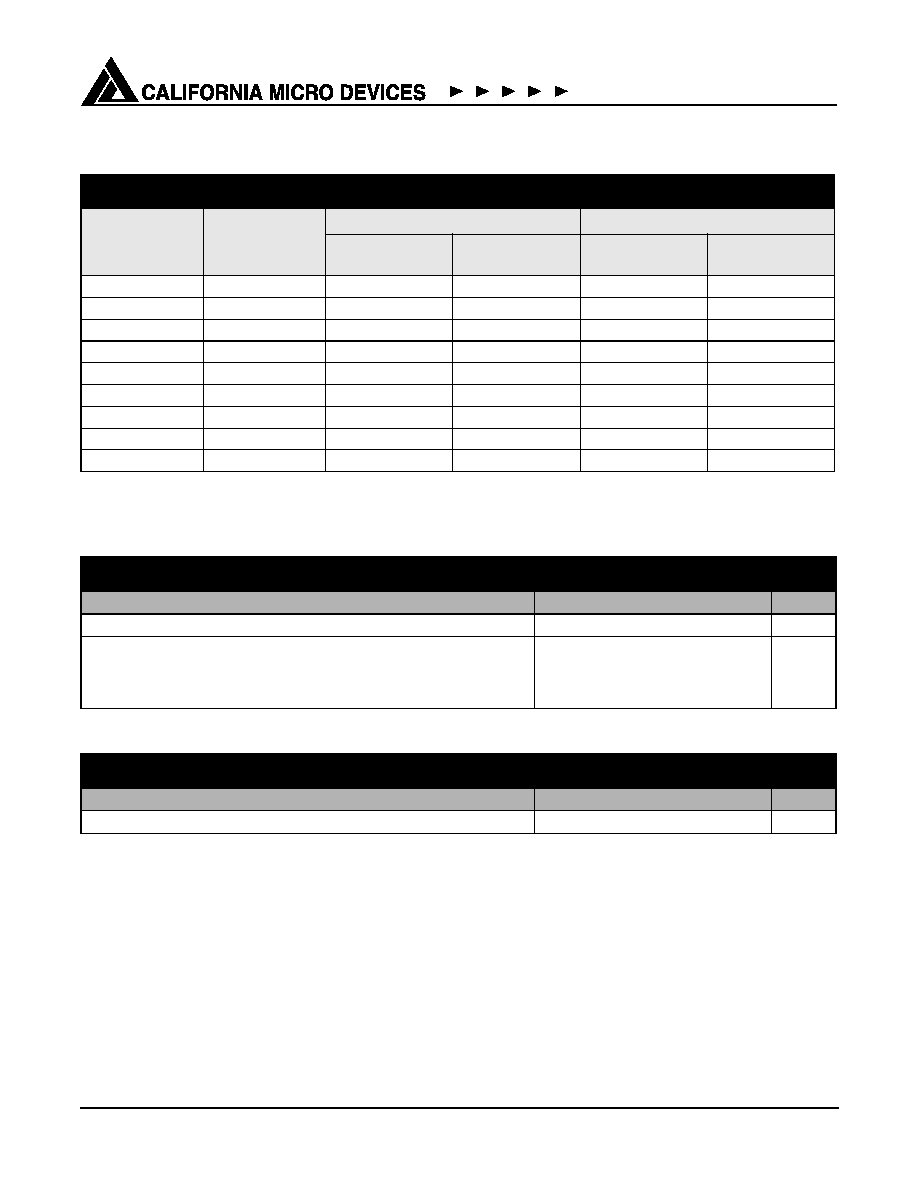
Ordering Information
Note 1: Parts are shipped in Tape & Reel form unless otherwise specified.
Specifications
PART NUMBERING INFORMATION
Bumps
Package
Standard Finish
Lead-free Finish
2
Ordering Part
Number
1
Part Marking
Ordering Part
Number
1
Part Marking
3
SOT23-3
PACDN042Y3
D042
PACDN042Y3R
D052
3
SC70-3
PACDN042YB3
D42
PACDN042YB3R
D52
4
SOT143
PACDN043Y4
D043
PACDN043Y4R
D053
5
SOT23-5
PACDN044Y5
D044
PACDN044Y5R
D054
5
SC70-5
PACDN044YB5
D44
PACDN044YB5R
D54
6
SOT23-6
PACDN045Y6
D045
PACDN045Y6R
D055
6
SC70-6
PACDN045YB6
D45
PACDN045YB6R
D55
8
TSSOP
PACDN044T
PACDN044T
PACDN044TR
PACDN054T
8
MSOP
PACDN046M
D046
PACDN046MR
D056
ABSOLUTE MAXIMUM RATINGS
PARAMETER
RATING
UNITS
Storage Temperature Range
-65 to +150
∞C
Package Power Dissipation
SC70
SOT23-3, SOT23-5, SOT23-6, SOT143
TSSOP, MSOP
0.2
0.225
0.5
W
W
W
STANDARD OPERATING CONDITIONS
PARAMETER
RATING
UNITS
Operating Temperature
-40 to +85
∞C

© 2003 California Micro Devices Corp. All rights reserved.
4
430 N. McCarthy Blvd., Milpitas, CA 95035-5112
L Tel: 408.263.3214
L Fax: 408.263.7846 L www.calmicro.com
11/26/03
PACDN042/43/44/45/46
Specifications (cont'd)
Note 1: Guaranteed by design and characterization.
Note 2: ESD voltage applied between channel pins & ground, one pin at a time; all other channel pins open; all GND pins grounded.
ELECTRICAL OPERATING CHARACTERISTICS
SYMBOL PARAMETER
CONDITIONS
MIN
TYP
MAX
UNITS
C
Capacitance T
A
= 25∞C, 2.5VDC, 1MHz
30
pF
V
RSO
Reverse Stand-off Voltage
I
R
=10
µA, T
A
= 25∞C
5.5
V
I
R
=1mA, T
A
= 25∞C
6.1
V
I
LEAK
Leakage Current
V
IN
=5.0VDC, T
A
= 25∞C
1
100
nA
V
SIG
Small Signal Clamp Voltage
Positive Clamp
Negative Clamp
I = 10mA, T
A
= 25∞C
I = -10mA, T
A
= 25∞C
6.2
-0.4
6.8
-0.8
8
-1.2
V
V
V
ESD
ESD Withstand Voltage
Human Body Model, MIL-STD-883,
Method 3015
Contact Discharge per IEC 61000-4-2
standard
Notes 1 & 2
Notes 1 & 2
+30
+20
kV
kV
V
CL
Clamping Voltage during ESD Discharge
+8kV Discharge
-8kV Discharge
MIL-STD-883D, Method 3015
12
-8
V
V
R
D
Diode Dynamic Resistance
Forward Conduction
Reverse Conduction
1.0
1.4

© 2003 California Micro Devices Corp. All rights reserved.
11/26/03
430 N. McCarthy Blvd., Milpitas, CA 95035-5112
L Tel: 408.263.3214
L Fax: 408.263.7846
L www.calmicro.com
5
PACDN042/43/44/45/46
Performance Information
Diode Capacitance
Typical diode capacitance with respect to positive TVS cathode voltage (reverse voltage across the diode) is given
in
Figure 1
.
Figure 1. Diode Capacitance vs. Reverse Voltage
Typical High Current Diode Characteristics
Measurements are made in pulse mode with a nominal pulse width of 0.7mS.
Diode Reverse Voltage (V)
Diode Capacitance (pF)
0
60
50
40
30
20
10
0
1
2
3
4
5
Typical Input VI Characteristics
(Pulse-mode measurements, pulse width = 0.7mS nominal)
-1.6
-1.4
-1.2
-1.0
-0.8
-0.6
-0.4
-0.2
0.0
0.2
0.4
0.6
0.8
1.0
1.2
1.4
1.6
-3
-2
-1
0
1
2
3
4
5
6
7
8
9
Input Voltage (V)
Input Current (A)
R
D
=
1
slope
R
D
=
1
slope

© 2003 California Micro Devices Corp. All rights reserved.
6
430 N. McCarthy Blvd., Milpitas, CA 95035-5112
L Tel: 408.263.3214
L Fax: 408.263.7846 L www.calmicro.com
11/26/03
PACDN042/43/44/45/46
Mechanical Details
PACDN042/43/44/45/46 devices are packaged in the
following packages: SOT23-3, SOT23-5, SOT23-6,
SC70-3, SC70-5, SC70-6, SOT143, TSSOP-8, and
MSOP-8.
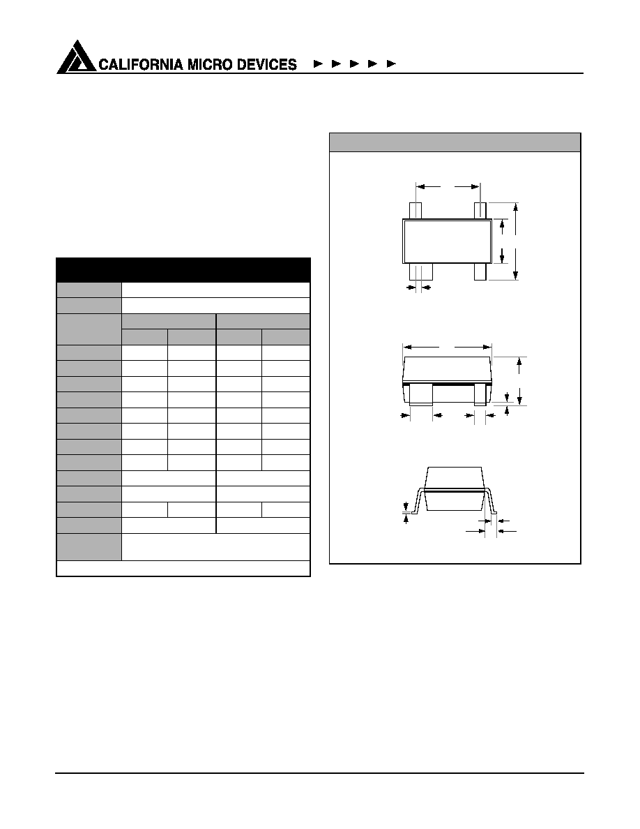
SOT23-3 Mechanical Specifications
Dimensions for PACDN042Y3 and PACDN042Y3R
devices packaged in 3-pin SOT23 packages are pre-
sented below.
For complete information on the SOT23-3 package,
see the California Micro Devices SOT23 Package Infor-
mation document.
Package Dimensions for SOT23-3.
PACKAGE DIMENSIONS
Package
SOT23-3 (JEDEC name is TO-236)
Pins
3
Dimensions
Millimeters
Inches
Min
Max
Min
Max
A
0.89
1.12
0.0350
0.0441
A1
0.01
0.10
0.0004
0.0039
b
0.30
0.50
0.0118
0.0197
c
0.08
0.20
0.0031
0.0079
D
2.80
3.04
0.1102
0.1197
E
2.10
2.64
0.0827
0.1039
E1
1.20
1.40
0.0472
0.0551
e
0.95 BSC
0.0374 BSC
e1
1.90 BSC
0.0748 BSC
L
0.40
0.60
0.0157
0.0236
L1
0.54 REF
0.0213 REF
# per tape
and reel
3000 pieces
Controlling dimension: millimeters
Mechanical Package Diagrams
TOP VIEW
e
E1 E
A
SIDE VIEW
L1
END VIEW
D
A1
c
1
2
e1
b
L
3

© 2003 California Micro Devices Corp. All rights reserved.
11/26/03
430 N. McCarthy Blvd., Milpitas, CA 95035-5112
L Tel: 408.263.3214
L Fax: 408.263.7846
L www.calmicro.com
7
PACDN042/43/44/45/46
Mechanical Details (continued)
SC70-3 Mechanical Specifications:
Dimensions for PACDN042YB3 and PACDN042YB3R
devices packaged in 3-pin SC70 packages are pre-
sented below.
For complete information on the SC70-3 package, see
the California Micro Devices SC70 Package Informa-
tion document.
* This is an approximate amount which may vary.
Package Dimensions for SC70-3.
PACKAGE DIMENSIONS
Package
SC70 (JEDEC name is MO-203 Issue A)
Pins
3
Dimensions
Millimeters
Min
Max
A
0.80
1.10
A1
0.00
0.10
A2
0.70
1.00
B
0.15
0.30
c
0.08
0.25
D
1.85
2.25
E
1.15
1.35
e
0.65 BSC
HE
2.00
2.40
L
0.26
0.46
# per bag
1000 pieces*
# per tape and
reel
3000 pieces*
Mechanical Package Diagrams
TOP VIEW
e
E
HE
A
SIDE VIEW
L
END VIEW
D
A1
c
1
2
B
e
A2
3
© 2003 California Micro Devices Corp. All rights reserved.
8
430 N. McCarthy Blvd., Milpitas, CA 95035-5112
L Tel: 408.263.3214
L Fax: 408.263.7846 L www.calmicro.com
11/26/03
PACDN042/43/44/45/46
Mechanical Details (continued)
SOT143 Mechanical Specifications
Dimensions for PACDN043Y4 and PACDN043Y4R
devices packaged in 4-pin SOT143 packages are pre-
sented below.
For complete information on the SOT143 package, see
the California Micro Devices SOT143 Package Infor-
mation document.
* This is an approximate amount which may vary.
Package Dimensions for SOT143.
PACKAGE DIMENSIONS
Package
SOT143
Pins
4
Dimensions
Millimeters
Inches
Min
Max
Min
Max
A
0.80
1.22
0.031
0.048
A1
0.05
0.15
0.002
0.006
b
0.30
0.50
0.012
0.019
b2
0.76
0.89
0.030
0.035
c
0.08
0.20
0.003
0.008
D
2.80
3.04
0.110
0.119
E
2.10
2.64
0.082
0.103
E1
1.20
1.40
0.047
0.055
e
1.92 BSC
0.075 BSC
e1
0.20 BSC
0.008 BSC
L
0.4
0.6
0.016
0.024
L1
0.54 REF
0.021 REF
# per tape
and reel
3000 pieces*
Controlling dimension: millimeters
Mechanical Package Diagrams
TOP VIEW
4
3
e
E1 E
b2
A
SIDE VIEW
L
END VIEW
D
A1
c
1
2
b
e1
L1

© 2003 California Micro Devices Corp. All rights reserved.
11/26/03
430 N. McCarthy Blvd., Milpitas, CA 95035-5112
L Tel: 408.263.3214
L Fax: 408.263.7846
L www.calmicro.com
9
PACDN042/43/44/45/46
Mechanical Details (continued)
SOT23-5 Mechanical Specifications
Dimensions for PACDN044Y5 and PACDN044Y5R
devices packaged in 5-pin SOT23 packages are pre-
sented below.
For complete information on the SOT23-5 package,
see the California Micro Devices SOT23 Package Infor-
mation document.
* This is an approximate amount which may vary.
Package Dimensions for SOT23-5.
PACKAGE DIMENSIONS
Package
SOT23-5 (JEDEC name is MO-178)
Pins
5
Dimensions
Millimeters
Inches
Min
Max
Min
Max
A
--
1.45
--
0.057
A1
0.00
0.15
0.000
0.006
b
0.30
0.50
0.012
0.020
c
0.08
0.22
0.003
0.009
D
2.75
3.05
0.108
0.120
E
2.60
3.00
0.102
0.118
E1
1.45
1.75
0.057
0.069
e
0.95 BSC
0.0374 BSC
e1
1.90 BSC
0.0748 BSC
L
0.60 REF
0.0236 REF
# per tape
and reel
3000 pieces*
Controlling dimension: inches
Mechanical Package Diagrams
TOP VIEW
5
4
e1
e
E1 E
b
A
SIDE VIEW
L1
END VIEW
D
A1
c
1
2
3

© 2003 California Micro Devices Corp. All rights reserved.
10
430 N. McCarthy Blvd., Milpitas, CA 95035-5112
L Tel: 408.263.3214
L Fax: 408.263.7846 L www.calmicro.com
11/26/03
PACDN042/43/44/45/46
Mechanical Details (continued)
SC70-5 Mechanical Specifications:
Dimensions for PACDN044YB5 and PACDN044YB5R
devices packaged in 5-pin SC70 packages are pre-
sented below.
For complete information on the SC70-5 package, see
the California Micro Devices SC70 Package Informa-
tion document.
* This is an approximate amount which may vary.
Package Dimensions for SC70-5
PACKAGE DIMENSIONS
Package
SC70-5
(JEDEC name is MO-203 Issue A)
Pins
5
Dimensions
Millimeters
Min
Max
A
0.80
1.10
A1
0.00
0.10
A2
0.70
1.00
B
0.15
0.30
c
0.08
0.25
D
1.85
2.25
E
1.15
1.35
e
0.65 BSC
HE
2.00
2.40
L
0.26
0.46
# / bag
1000 pieces*
# / tape and reel
3000 pieces*
Mechanical Package Diagrams
TOP VIEW
e
e
E HE
B
A
SIDE VIEW
L
END VIEW
D
A2
A1
c
5
4
1
2
3

© 2003 California Micro Devices Corp. All rights reserved.
11/26/03
430 N. McCarthy Blvd., Milpitas, CA 95035-5112
L Tel: 408.263.3214
L Fax: 408.263.7846
L www.calmicro.com
11
PACDN042/43/44/45/46
Mechanical Details (continued)
SOT23-6 Mechanical Specifications:
Dimensions for PACDN045Y6 and PACDN045Y6R
devices packaged in 6-pin SOT23 packages are pre-
sented below.
For complete information on the SOT23-6 package,
see the California Micro Devices SOT23 Package Infor-
mation document.
* This is an approximate amount which may vary.
Package Dimensions for SOT23-6.
PACKAGE DIMENSIONS
Package
SOT23 (JEDEC name is MO-178)
Pins
6
Dimensions
Millimeters
Inches
Min
Max
Min
Max
A
--
1.45
--
0.057
A1
0.00
0.15
0.000
0.006
b
0.30
0.50
0.012
0.020
c
0.08
0.22
0.003
0.009
D
2.75
3.05
0.108
0.120
E
2.60
3.00
0.102
0.118
E1
1.45
1.75
0.057
0.069
e
0.95 BSC
0.0374 BSC
e1
1.90 BSC
0.0748 BSC
L
0.60 REF
0.0236 REF
# per tape
and reel
3000 pieces*
Controlling dimension: inches
Mechanical Package Diagrams
TOP VIEW
A
SIDE VIEW
D
A1
L1
END VIEW
c
L
1
2
3
6
5
4
e1
e
E1 E
b
Pin 1
Marking

© 2003 California Micro Devices Corp. All rights reserved.
12
430 N. McCarthy Blvd., Milpitas, CA 95035-5112
L Tel: 408.263.3214
L Fax: 408.263.7846 L www.calmicro.com
11/26/03
PACDN042/43/44/45/46
Mechanical Details (continued)
SC70-6 Mechanical Specifications:
Dimensions for PACDN045YB6 and PACDN045YB6R
devices packaged in 6-pin SC70 packages are pre-
sented below.
For complete information on the SC70-6 package, see
the California Micro Devices SC70 Package Informa-
tion document.
* This is an approximate amount which may vary.
Package Dimensions for SC70-6.
PACKAGE DIMENSIONS
Package
SC70-6
(JEDEC name is MO-203 Issue A)
Pins
6
Dimensions
Millimeters
Min
Max
A
0.80
1.10
A1
0.00
0.10
A2
0.70
1.00
B
0.15
0.30
c
0.08
0.25
D
1.85
2.25
E
1.15
1.35
e
0.65 BSC
HE
2.00
2.40
L
0.26
0.46
# / bag
1000 pieces*
# / tape and reel
3000 pieces*
Mechanical Package Diagrams
TOP VIEW
1
2
3
6
5
4
e
e
B
A
SIDE VIEW
L
END VIEW
D
A2
A1
c
E1 E
Pin 1
Marking
© 2003 California Micro Devices Corp. All rights reserved.
11/26/03
430 N. McCarthy Blvd., Milpitas, CA 95035-5112
L Tel: 408.263.3214
L Fax: 408.263.7846
L www.calmicro.com
13
PACDN042/43/44/45/46
Mechanical Details (continued)
TSSOP-8 Mechanical Specifications:
Dimensions for PACDN044T and PACDN044TR
devices packaged in 8-pin TSSOP packages are pre-
sented below.
For complete information on the TSSOP-8 package,
see the California Micro Devices TSSOP Package
Information document.
* This is an approximate amount which may vary.
Package Dimensions for TSSOP-8
PACKAGE DIMENSIONS
Package
TSSOP
Pins
8
Dimensions
Millimeters
Inches
Min
Max
Min
Max
A
--
1.10
--
0.0433
A1
0.05
0.15
0.002
0.006
B
0.19
0.30
0.0075
0.0118
C
0.09
0.20
0.0035
0.0079
D
2.90
3.10
0.114
0.122
E
6.25
6.50
0.246
0.256
E1
4.30
4.50
0.169
0.177
e
0.65 BSC
0.0256 BSC
L
0.50
0.70
0.020
0.028
# per tube
74 pcs*
# per tape
and reel
2500 pcs
Controlling dimension: millimeters
Mechanical Package Diagrams
E1
D
E
TOP VIEW
L
END VIEW
C
B
A
A1
SEATING
PLANE
1
2
3
4
8
7
6
5
e
SIDE VIEW
Pin 1 Marking

© 2003 California Micro Devices Corp. All rights reserved.
14
430 N. McCarthy Blvd., Milpitas, CA 95035-5112
L Tel: 408.263.3214
L Fax: 408.263.7846 L www.calmicro.com
11/26/03
PACDN042/43/44/45/46
Mechanical Details (continued)
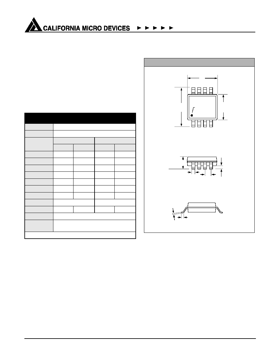
MSOP-8 Mechanical Specifications:
Dimensions for PACDN046M and PACDN046MR
devices packaged in 8-pin MSOP packages are pre-
sented below.
For complete information on the MSOP-8 package, see
the California Micro Devices MSOP Package Informa-
tion document.
* This is an approximate amount which may vary.
Package Dimensions for MSOP-8
PACKAGE DIMENSIONS
Package
MSOP
Pins
8
Dimensions
Millimeters
Inches
Min
Max
Min
Max
A
0.87
1.17
0.034
0.046
A1
0.05
0.25
0.002
0.010
B
0.30 (typ)
0.012 (typ)
C
0.18
0.007
D
2.90
3.10
0.114
0.122
E
2.90
3.10
0.114
0.122
e
0.65 BSC
0.025 BSC
H
4.78
4.98
0.188
0.196
L
0.52
0.54
0.017
0.025
# per tube
80 pieces*
# per tape
and reel
4000 pieces
Controlling dimension: inches
Mechanical Package Diagrams
E
D
H
1
2
3
4
8
7
6
5
L
END VIEW
C
e
B
A
A1
SEATING
PLANE
SIDE VIEW
TOP VIEW
Pin 1
Marking