
NCX10S SERIES
Isolated 10W Single Output DC/DC Converters
www.cdpoweronline.com
SELECTION GUIDE
1
FEATURES
High Efficiency to 82%
500V Input to Output Isolation
Industry Standard Pinout
UL 60950 Recognition Pending
Non Latching Current Limit
Constant 400kHz Frequency
Versatile Control Options
Continuous Rating to 10W @85∞C
Operation to Zero Load
Protected Against Load Faults
Internal Over Temperature Protection
Uses No Electrolytic Capacitors
DESCRIPTION
The NCX10S series of DC/DC Converters
combines ease of application with versatility
and is available in two pin patterns based on
popular industry standards. High efficiency
enables full rating to be achieved in a small
package without heatsinking, and a high
surge capability will provide for start-up and
transient loads, whilst being thermally
protected against sustained overload. The
NCX10S series is currently undergoing
testing by Underwriters Laboratory (UL) to UL
60950 for functional insulation.
Order Code
V
V
A
mW
mW
%
pF
NCX10S24033
24
3.4
3.1
270
26
78
23
NCX10S24050
24
5.1
2.0
280
25
82
26
NCX10S48033
48
3.4
3.1
500
44
79
29
NCX10S48050
48
5.1
2.0
510
45
82
32
NCX10S24033Y
24
3.4
3.1
270
26
78
23
NCX10S24050Y
24
5.1
2.0
280
25
82
26
NCX10S48033Y
48
3.4
3.1
500
44
79
29
NCX10S48050Y
48
5.1
2.0
510
45
82
32
Parameter
Conditions
MIN
NOM
MAX
Units
Voltage Range
Continuous operation, 24V input types
18
24
36
V
Continuous operation, 48V input types
36
48
75
Nominal
Input V
o
ltage
Output V
o
ltage
Output Current
Power Consumption
at 0% Load
Power Consumption
at Shutdown
Efficiency (MIN)
Isolation
Capacitance
Parameter
Conditions
MIN
TYP
MAX
Units
Voltage Set Point Error 50% load
1.0
%
Overall
Substrate temperature ≠40 to 110∞C
Voltage Error
Load 0% - 100%
2.5
%
Input specified range
Temperature Coefficient
of Output Voltage
250
ppm∞C
(slope)
Deviation of
Output Voltage
Temperature MIN - MAX
1.0
%
Current Limit
Continuous short circuit causes no damage
NCX10S24033
153
% of
Overload
95% of nominal NCX10S24050
170
rated
Output Current
output voltage
NCX10S48033
148
Output
NCX10S48050
164
Current
Line Regulation
Operating voltage range, 50% load
0.1
%
Load Regulation
0% - 100% rated load
2
0.5
%
Ripple
rms
1.0
%
Input voltage, 24V input types
≠0.3V to 40V
Input voltage, 48V input types
≠0.3V to 80V
Output Voltage
≠0.3V to regulated voltage
Output trim control
≠1V to +30V relative to output return
Shutdown control
≠0.3V to 6V relative to input return
INPUT CHARACTERISTICS
1
OUTPUT CHARACTERISTICS
1
Parameter
Conditions
MIN
TYP
MAX
Units
Voltage Trimming
At rated load,
±10
%
Range
Trim control at either output
Remote Switch Input
Not operating
-0.3
0
1.5
(voltage relative
Operating, open circuit voltage
2.6
5.0
6.1
V
to input negative)
V
IN
MIN to MAX
Start Delay
Time from application of valid input
voltage to output being in specification
10
ms
Switching Frequency
360
400
440
kHz
CONTROL CHARACTERISTICS
ABSOLUTE MAXIMUM RATINGS
1 Specifications typical at T
A
=25∞C, nominal input voltage and rated output current unless otherwise specified.
2 A minimum load of 10% of rating is recommended for typical applications, see application notes.
ENVIRONMENTAL CHARACTERISTICS
APPLICATION NOTES
Parameter
Conditions
MIN
TYP
MAX
Units
Substrate Temp.
Full load
≠40
125
∞C
Storage
Absolute MAX internal temperature
≠40
125
∞C
Thermal Protection Operates at substrate temperature
150
∞C
In a typical application, the NCX10S series
of DC/DC converters require nothing more
than a dc supply of correct polarity and
voltage to generate its specified output. These
notes are intended to offer help in the use of
other facilities offered by these converters,
and to provide assistance in achieving their
full potential.
VOLTAGE TRIMMING
ISOLATION CHARACTERISTICS
Parameter
Conditions
MIN
TYP
MAX
Units
Isolation Voltage
Flash tested for 1 second
1000
VDC
Resistance
V
ISO
=500VDC
1
G
THERMAL PERFORMANCE
11
10
9
8
7
6
5
4
-40
10
60
110
Ambient Temperature (∞C)
NCX10S24033
Ambient Power (W)
Still Air
100lfm
200lfm
300lfm
400lfm
11
10
9
8
7
6
5
4
-40
10
60
110
Ambient Temperature (∞C)
NCX10S24050
Ambient Power (W)
Still Air
100lfm
200lfm
300lfm
11
10
9
8
7
6
5
4
-40
10
60
110
Ambient Temperature (∞C)
NCX10S48033
Ambient Power (W)
Still Air
100lfm
200lfm
11
10
9
8
7
6
5
4
-40
10
60
110
Ambient Temperature (∞C)
NCX10S48050
Ambient Power (W)
Still Air
100lfm
UL 60950 RECOGNITION
(Maximum permissable load in still air)
Part Number
-40∞C
25∞C
70∞C
75∞C
80∞C
85∞C
90∞C
Units
NCX10S24033
10.0
10.0
10.0
9.0
7.9
6.5
5.0
NCX10S24050
10.0
10.0
10.0
10.0
8.9
7.2
5.2
W
NCX10S48033
10.0
10.0
10.0
9.5
8.4
7.1
5.5
NCX10S48050
10.0
10.0
10.0
10.0
10.0
9.6
8.0
NCX10S SERIES
Isolated 10W Single Output DC/DC Converters
DC
DC
+V
IN
≠V
IN
+V
OUT
ADJ
100K
0V
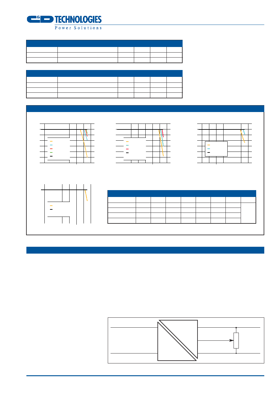
Figure 1: Voltage Trimming
The trimming (adjust) input on the secondary
side allows output voltage adjustment within
the capability of the power circuit.
When open circuit, the trimming pin ADJ
operates at near half the output voltage. A
basic trimming arrangement consists of a
potentiometer of 10k to 100k connected
across the output, with its wiper connected to
the ADJ pin (see figure 1). Dependent on
model, the output will be reduced by about
15% when the wiper is at the positive output,
or increased by about 24% when at the
negative rail. Regulation will be maintained to
at least 10% adjustment either way.
If finer adjustment is required, a resistor may
be included between the wiper and the pin.
For example, 62k will restrict a 3.3V model
to ±5% adjustment range. The corresponding
values for the 5V model is 56k.
SET VOLTAGE
The output voltage is set to 100mV above
nominal, to offset resistive losses and thus
assist with worst case error calculations. This
allowance can be altered with a single fixed
resistor, connected from the trimming pin to
one of the output pins.
OTHER TRIMMING FUNCTIONS
The voltage applied to the trim pin need not
be from a potentiometer. The trim facility may
be driven electronically to provide
"margining", remote sense, active load
sharing, current control or remote
programming (There is a minimum output
voltage below which control is not possible).
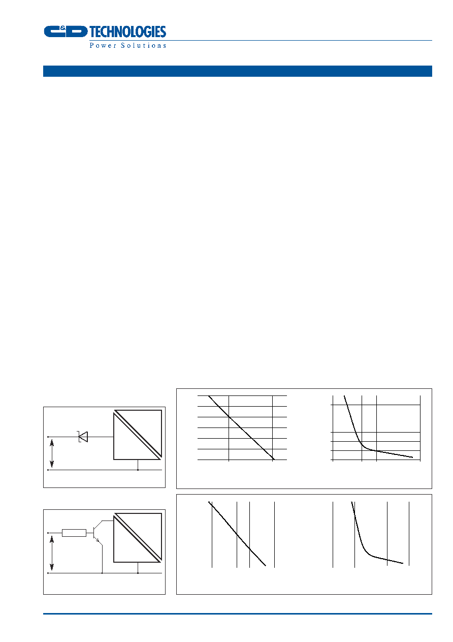
SHUTDOWN & UNDER VOLTAGE TRIM
When the shutdown pin (Pin 11) is shorted to
the negative input, the converter will stop. Its
current consumption will then be less than
1mA at nominal supply voltage. The
shutdown/UV adjust pin serves the dual
function of shutting the converter down into a
low power state, and allowing adjustment of
the under voltage start threshold.
To shut the unit down this pin should be taken
to below 1.5V, using either an isolating
diode (figure 2) with the anode connected to
the shutdown pin or using an open collector
pulldown (figure 3).
The UV threshold can be controlled either via
a resistor connected between the pin and 0V,
or by connecting a series 1M resistor to a
voltage of between 0V and 2.5V.
The variation of startup voltage with either
parallel resistor or applied voltage is shown
in figures 4 & 5. Note that voltage should not
be applied directly to the pin without a series
resistor or diode.
If the shutdown pin is to be connected to a
long wire, it is recommended that a capacitor
decouples the pin to the supply common in
order to avoid the risk of injecting noise into
the converter circuit. A series resistor may
also be helpful. Values of 10nF and 1k may
be used.
Many converters may be switched together
simply by linking the primary control pins via
a schottky signal diode anode to the control
pin. The primary common pins must also be
linked, see figure 6.
FILTERING
The module includes a basic level of filtering,
sufficient for many applications. Where lower
noise levels are desired, filters can easily be
added to achieve any required noise
performance.
A DC/DC converter generates noise in two
principle forms: that which is radiated from
its body and that conducted on its external
connections. There are three separate modes
of conducted noise: input differential, output
differential and input-output.
This last appears as common mode at the
input and the output, and cannot therefore be
removed by filtering at the input or output
alone. The first level of filtering is to connect
a capacitor between input and output returns,
to reduce this form of noise. It typically
contains high harmonics of the switching
frequency, which tend to appear as spikes on
surrounding circuits. The voltage rating of this
capacitor must match the required isolation
voltage. (Due to the great variety in isolation
voltage and required noise performance, this
capacitor has not been included within the
converter.)
Input ripple is a voltage developed across the
internal input decoupling capacitor. It is
therefore measured with a defined supply
source impedance. Although simple series
inductance will provide filtering, on its own it
can degrade the stability. A shunt capacitor is
therefore recommended across the converter
input terminals, so that it is fed from a low
impedance.
If no filtering is required, the inductance of
long supply wiring could also cause a
problem, requiring an input decoupling
capacitor for stability. An electrolytic will
perform well in these situations.
See figure 7 for a recommended
configuration to reduce all three conducted
modes.
The component values and ratings will
depend on the converter rating and voltage,
and the required noise performance. The
input-output filtering is performed by the
common-mode choke on the primary. This
could be placed on the output, but would
then degrade the regulation and produce less
2.5
2.0
1.5
1.0
17
17.5
18
18.5
19
19.5
20
Startup Voltage (V)
Applied V
o
ltage (V)
15
13
11
9
7
5
3
1
17
17.5
18
18.5
19
19.5
20
Startup Voltage (V)
Shutdown Resistor (M
)
NCX10S SERIES
Isolated 10W Single Output DC/DC Converters
Figure 2: Shutdown with Isolating Diode
Figure 3: Shutdown with Open Collector
Pulldown
Figure 4: NCX10S24XXX Startup Voltage Vs Startup Pin Resistor/Voltage
2.5
2.0
1.5
1.0
32.5 33 33.5 34 34.5 35 35.5 36
Startup Voltage (V)
Applied V
o
ltage (V)
15
13
11
9
7
5
3
1
32
33
34
35
36
Startup Voltage (V)
Shutdown Resistor (M
)
Figure 5: NCX10S48XXX Startup Voltage Vs Startup Pin Resistor/Voltage
APPLICATION NOTES
DC
DC
≠V
IN
SD
e.g. BAT42
Less than 0.8V
for Shutdown
DC
≠V
IN
SD
e.g. BC546
Greater than 1.5V
for Shutdown
10K 0.25W
DC
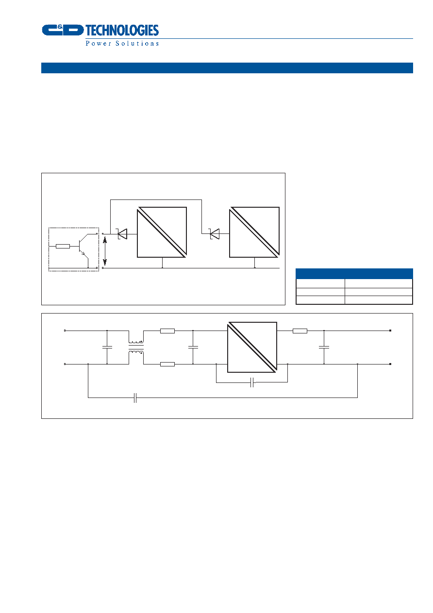
1 Anti surge T-type fuses are recommended
FUSING
Part Number
Recommended Fuses
1
NCX10S24XX
1.6A
NCX10S48XX
1.0A
benefit for a given size, cost, and power loss.
Radiated noise is present in magnetic and
electrostatic forms. Thanks to the small size of
these units, neither form of noise will be
radiated "efficiently", so will not normally
cause a problem. Any question of this kind
usually better repays attention to conducted
signals.
In applications where large transient load
swings are expected, for example 10-60% or
25-75%, the fitting of an external electrolytic
output capacitor is recommended to reduce
voltage over/under shoot. 200µF capacitance
will typically reduce a peak excursion to
350mV settling to within 1% V
NOM
in 1.2ms.
Additional externally fitted capacitance will
further reduce over/under shoot.
PROTECTION
The "absolute maximum" ratings in the
specification define conditions which may
degrade life but will not result in immediate
damage. This section of the application notes
deals with those unavoidable or accidental
occasions when the ratings are exceeded.
The unit will protect itself against a wide
range of abnormal conditions. In others,
where failure is inevitable, the consequent
hazards have been minimised.
If the supply polarity is reversed, the unit is
unable to protect itself. The simple
preventative measure of a series diode would
add unacceptable power loss for the basic
product, but it may be appropriate in some
applications to fit this diode externally.
With no polarity protection, tracks and
components will safely fail to high
impedance, disconnecting the power. A large
fault current will occur in this process.
NCX10S SERIES
Isolated 10W Single Output DC/DC Converters
APPLICATION NOTES
Figure 6: Shutdown with Isolating Diode
DC
≠V
IN
2.2µF
2.2µF
100µH
10µH
10µH
10µF, 250Vac Y Rated
10µF, 250Vac Y Rated
100µH
1mH
SD
Less than
0.8V for
Shutdown
Optional Open
Collector Transistor
DC
DC
≠V
IN
SD
DC
Figure 7: Recommended Configuration to Reduce Noise
DC
DC
C&D Technologies (NCL) Ltd
Tanners Drive, Blakelands North
Milton Keynes MK14 5BU, England
Tel: +44 (0)1908 615232
Fax: +44 (0)1908 617545
email: info@cdtechno-ncl.com
www.cdpoweronline.com
C&D Technologies Inc.
3400 E Britannia Drive, Tucson,
Arizona 85706, USA
Tel: +1 (800) 547-2537
Fax: +1 (520) 741-4598
email: pedmktg@cdtechno.com
C&D Technologies (NCL) Limited reserve the right to alter or improve the
specification, internal design or manufacturing process at any time, without
notice. Please check with your supplier or visit our web site to ensure that
you have the current and complete specification for your product before use.
© C&D Technologies (NCL) Limited 2003
NDC NCX10S.1
No part of this publication may be copied, transmitted or stored in a
retrieval system or reproduced in any way including, but not limited to,
photography, photocopy, magnetic or other recording means, without prior
written permission from C&D Technologies (NCL) Limited.
Instructions for use are available from www.cdpoweronline.com
MECHANICAL DIMENSIONS
NCX10S SERIES
Isolated 10W Single Output DC/DC Converters
0.20 (5.0)
0.01 (2.51) MAX
0.20 (5.00)
1.57 (40.0)
0.14 (3.60)
0.10±0.004
(2.59±0.1)
1.58 (40.03)
1.12 ±0.016
(28.4 ±0.4)
0.82
(20.75)
1.17
(29.6)
0.94
(24.0)
0.31
(7.75)
MAX
0.008(0.2) M
P
S
S
0.004(0.1)
18 Pins
0.09±0.001 (2.27±0.25)
DETAIL A
S
0.010±0.002
(0.25±0.05)
REFERENCE PLANE
0.049±0.008
(1.24±0.2)
x18 Pins
0.197
(0.50)
±5.00∞
0.008(0.2) M
P
S
Detail A
Recommended Footprint Details
Pin Connections
1
18
17
16
15
14
13
12
11
10
2
3
4
5
6
7
8
9
All pins on a 0.1(2.54) pitch and within
±0.01(0.25) of true position.
Unless otherwise stated all dimensions in
inches(mm) ±0.01(0.25).
PIN
NCX10SXXXXX NCX10SXXXXXY
1
+V
OUT
+V
OUT
2
≠V
OUT
≠V
OUT
3-7
NC
NC
8
V
ADJ
V
ADJ
9-10
NC
NC
11
SD
SD
12-16
NC
NC
17
≠V
IN
+V
IN
18
+V
IN
≠V
IN
Package Weight: 8.3g
1.75 (44.56)
18 Pin SMD Package Style
0.315±0.004
(8.00±0.10)