 | –≠–ª–µ–∫—Ç—Ä–æ–Ω–Ω—ã–π –∫–æ–º–ø–æ–Ω–µ–Ω—Ç: NDY0509 | –°–∫–∞—á–∞—Ç—å:  PDF PDF  ZIP ZIP |
www.cdpoweronline.com
SELECTION GUIDE
FEATURES
Industry Standard Footprint
Single Isolated Output
Short Circuit Protection
Operating Temperature Range
-40∞C to +85∞C
Low Profile 24 Pin Case
Efficiency to 82%
Power Density 0.90W/cm
3
2:1 Wide Input Range
5V, 12V, 24V & 48V Input
3.3V, 5V, 9V, 12V & 15V Output
Footprint 4.73cm
2
UL 94V-0 Package Materials
No Heatsink Required
Internal SMD Construction
Fully Encapsulated
Lead Free Compatible
DESCRIPTION
The NDY series is a range of low profile
DC/DC converters offering a single regulated
output over a 2:1 input voltage range. All
parts deliver 3W output power up to 85∞C
without heatsinking, except the 4.5V to 9V
input voltage range which should be derated
to 2W at the lower input voltage. A flyback
oscillator design with isolated feedback is
used to give regulation over the full operating
range of 25% to 100% of full load. It is
strongly recommended that external
capacitors be used on input and output to
guarantee performance over full load and
input voltage range (see recommended filter
circuit for values). The plastic case and
encapsulant materials are rated to UL 94V-0
and the connection pins are formed from a
tin plated alloy 42 leadframe.
Nominal Rated
Input
Input
Output
Output Current
4
Current
Voltage Voltage
Min Load
Full Load
Full Load
MTTF
3
Order Code
(V)
(V)
(mA)
(mA)
(mA)
(%)
(pF)
kHrs
NDY0505
5
5
100 -150
400- 600
615
66
40
1939
NDY0509
5
9
55-83
222-333
563
72
52
1926
NDY0512
5
12 42-62
166-250
548
71
43
1907
NDY0515
5
15
33-50
133-200
533
73
44
1924
NDY1205
12
5
150
600
362
71
36
1928
NDY1209
12
9
83
333
320
78
52
1916
NDY1212
12
12
62
250
316
78
44
1897
NDY1215
12
15
50
200
308
79
47
1914
NDY2403
24
3.3
227
909
178
70
30
1671
NDY2405
24
5
150
600
174
70
36
1673
NDY2409
24
9
83
333
156
78
52
1663
NDY2412
24
12
62
250
154
80
44
1644
NDY2415
24
15
50
200
150
82
54
1657
NDY4803
48
3.3
227
909
87
71
30
1676
NDY4805
48
5
150
600
87
73
35
1668
NDY4809
48
9
83
333
78
80
52
1663
NDY4812
48
12
62
250
77
81
44
1648
NDY4815
48
15
50
200
76
81
53
1661
Min
Efficiency
1
T
ypical
Isolation
Capacitance
Parameter
Conditions
MIN
TYP
MAX
Units
All NDY05XX
4.5
5
9
Voltage Range
All NDY12XX
9
12
18
VDC
All NDY24XX
18
24
36
All NDY48XX
36
48
72
NDY2403
2
180
360
NDY4803
2
140
290
Reflected
1
All NDY05XX
400
500
Ripple
All NDY12XX
150
170
mA p-p
Current
All other NDY24XX
290
360
All other NDY48XX
100
127
Short-circuit protection
continuous
Input voltage 05 types
10V
Input voltage 12 types
20V
Input voltage 24 types
40V
Input voltage 48 types
80V
Lead temperature 1.5mm from case for 10 seconds
300∞C
Minimum Load
25% of rated load
Internal Dissipation
1.7W
INPUT CHARACTERISTICS
ABSOLUTE MAXIMUM RATINGS
1 Measured at full load with external input/output capacitors, refer to filter circuit 1.
2 For lower ripple refer to filter circuit 2.
3 Calculated using MIL-HDBK-217F with nominal input voltage at full load.
4 Refer to power derating graph.
All specifications typical at T
A
=25∞C, nominal input voltage and rated output current unless otherwise specified.
NDY SERIES
Isolated 3W Wide Input DC/DC Converters

Parameter
Conditions
MIN
TYP
MAX
Units
Voltage Set Point Accuracy
With external input/output capacitors, refer to filter circuits
±1
±5
%
Low line to high line, 3.3V output with external input/output capacitors,
0.05
0.2
%
Line Regulation
refer to filter circuit 1
Low line to high line, with external input/output capacitors,
0.05
0.5
%
refer to filter circuit 1
25% load to 100% load, 3.3V output with external input/output capacitors,
0.6
0.5
%
Load Regulation
refer to filter circuit 1
25% load to 100% load, with external input/output capacitors,
0.2
0.5
%
refer to filter circuit 1
BW = 20Hz to 300kHz. 3.3V output with external input/output capacitors,
80
120
mV rms
Ripple
2
refer to filter circuit 1
BW = 20Hz to 300kHz. With external input/output capacitors,
5
10
mV rms
refer to filter circuit 1
BW = DC to 100MHz. 3.3V output with external input/output capacitors,
180
mV p-p
Noise
refer to filter circuit 1
BW = DC to 100MHz. With external input/output capacitors,
50
100
mV p-p
refer to filter circuit 1
OUTPUT CHARACTERISTICS
www.cdpoweronline.com
1 Measured at full load with external input/output capacitors, refer to filter circuit 1.
2 For lower ripple refer to filter circuit 2.
3 Calculated using MIL-HDBK-217F with nominal input voltage at full load.
4 Refer to power derating graph.
All specifications typical at T
A
=25∞C, nominal input voltage and rated output current unless otherwise specified.
NDY SERIES
Isolated 3W Wide Input DC/DC Converters
ISOLATION CHARACTERISTICS
GENERAL CHARACTERISTICS
Parameter
Conditions
MIN
TYP
MAX
Units
Isolation Test Voltage
Flash tested for 1 second
1000
VDC
Resistance
Viso=500VDC
1
G
Parameter
Conditions
MIN
TYP
MAX
Units
100% load V
IN
nominal 3.3V output
160
220
Switching Frequency
25% load V
IN
nominal 3.3V output
290
560
kHz
100% load V
IN
nominal
80
220
25% load V
IN
nominal
290
560
Weight: 6.2g (3.3V O/P 6.7g)
PIN CONNECTIONS (TOP VIEW)
1.27 (32.26)
0.577
(14.66)
0.275
(7.00)
0.185 (4.70)
0.145 (3.70)
0.033 (0.84)
0.021 (0.54)
0.012 (0.30)
0.008 (0.20)
1
24
10
15
11
14
12
13
VIN
0V
+V
GND
VIN
0V
+V
GND
0.10
(2.54)
1.10 (27.94)
0.644
(16.35) Max
MECHANICAL DIMENSIONS
C&D Technologies (NCL) Ltd
Tanners Drive, Blakelands North
Milton Keynes MK14 5BU, England
Tel: +44 (0)1908 615232
Fax: +44 (0)1908 617545
email: info@cdtechno-ncl.com
www.cdpoweronline.com
C&D Technologies Inc.
3400 E Britannia Drive, Tucson,
Arizona 85706, USA
Tel: +1 (800) 547-2537
Fax: +1 (520) 741-4598
email: sales@cdtechno.com
C&D Technologies (NCL) Limited reserve the right to alter or improve the
specification, internal design or manufacturing process at any time, without
notice. Please check with your supplier or visit our web site to ensure that
you have the current and complete specification for your product before use.
© C&D Technologies (NCL) Limited 2003
NDC NDY.3
No part of this publication may be copied, transmitted or stored in a
retrieval system or reproduced in any way including, but not limited to,
photography, photocopy, magnetic or other recording means, without prior
written permission from C&D Technologies (NCL) Limited.
Instructions for use are available from www.cdpoweronline.com
NDY SERIES
Isolated 3W Wide Input DC/DC Converters
ENVIRONMENTAL
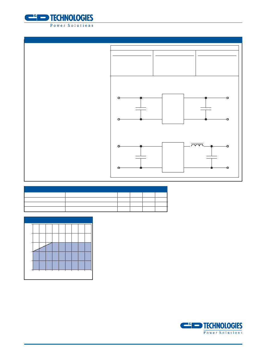
NDY05 POWER DERATING CURVE
Parameter
Conditions
MIN
TYP
MAX
Units
Operation
-40
85
∞C
Storage
-50
130
∞C
Cooling
Free air convection
5
4
3
2
1
0
4.5 5
6
7
8
9
Input Voltage (V)
Output Power (W)
FILTER CIRCUITS
EXTERNAL CAPACITANCE
Although these converters will work without
external capacitors, they are necessary in
order to guarantee the full parametric
performance over the full line and load
range. All parts have been tested and
characterised using the following values and
test circuit.
OUTPUT LOAD
The minimum rated load across the whole
input voltage range is 25% of the full load
output. It is important to take care that the
load does not fall below this as the output
ripple will greatly increase. While this
condition will not harm the device the
resultant increase in output ripple could cause
customers' application to malfunction.
Value
C
IN
10µF, 200V
Philips Part Number
151621809 or any
good low esr capacitor
C
OUT
100µF, 25V
Philips Part Number
13556101 or any good
low esr capacitor
L
OUT
C&D Technologies Part
No 24100
NDY
C
OUT
C
IN
V
IN
+V
OUT
GND
OV
FILTER CIRCUIT 1
FILTER CIRCUIT 2
Recommended circuit for reduced ripple 3.3V O/P
NDY
C
IN
C
OUT
V
IN
+V
OUT
GND
OV
L
OUT