NKA SERIES
Isolated Sub-Miniature 1W Dual Output DC-DC Converters
www.dc-dc.com
SELECTION GUIDE
FEATURES
s
New Sub-Miniature SIP & DIP
Package Styles
s
3kVDC Isolation
s
Efficiency up to 82%
s
Wide Temperature performance at
full 1 Watt load, ≠40∞C to 85∞C
s
Increased Power Density to
1.35W/cm
3
s
UL 94V-0 Package Material
s
Reduced Footprint at 0.98cm
2
s
Dual Output from a Single Input Rail
s
Industry Standard Pinout
s
Power Sharing on Output
s
3.3V, 5V & 12V Input
s
3.3V, 5V, 9V, 12V and 15V Output
s
No Heatsink Required
s
Internal SMD Construction
s
Fully Encapsulated with Toroidal
Magnetics
s
No External Components Required
s
MTTF up to 1.6 Million hours
s
No Electrolytic or Tantalum
Capacitors
DESCRIPTION
The NKA sub-miniature series of industrial
temperature range DC-DC converters are the
standard building blocks for on-board
distributed power systems. The series offers
smaller package size, improved efficiency,
lower output ripple and 3kVDC isolation
capability through the use of state of the art
packaging and technology. Ideally suited for
providing dual rail supplies on primarily
digital boards with the added benefit of
galvanic isolation to reduce switching noise.
All of the rated power may be drawn from a
single pin provided the total load does not
exceed 1watt.
Nominal
Input
Input
Output
Output
Current at
Isolation
Voltage
Voltage
Current
Rated Load Efficiency
Capacitance MTTF
1
OrderCode
(V)
(V)
(mA)
(mA)
(%)
(pF)
kHrs
NKA0303S
3.3
3.3
±163
407
74
20
195
NKA0305S
3.3
5
±100
383
79
22
1121
NKA0312S
3.3
12
±42
390
78
31
375
NKA0315S
3.3
15
±33
384
79
32
206
NKA0503S
5
3.3
±163
259
77
20
205
NKA0505S
5
5
±100
285
70
21
1697
N K A 0 5 0 5 S E
5
5
±100
249
80
26
1557
NKA0509S
5
9
±55
263
76
25
682
NKA0512S
5
12
±42
255
78
28
343
NKA0515S
5
15
±33
253
79
29
188
NKA1205S
12
5
±100
112
74
33
559
NKA1209S
12
9
±55
106
79
48
375
NKA1212S
12
12
±42
104
81
55
243
NKA1215S
12
15
±33
102
82
60
154
For DIP package style replace suffix S with D, eg NKA0312D.
When operated with additional external load capacitance the rise time of the input voltage will determine the
maximum external capacitance value for guaranteed start up. The slower the rise time of the input voltage the
greater the maximum value of the additional external capacitance for reliable start up.
1 Calculated using MIL-HDBK-217F with nominal input voltage at full load.
2 See derating curve.
3 12V input types have typically 3% less load regulation change.
4 Supply voltage must be discontinued at the end of the short circuit duration.
All specifications typical at T
A
=25∞C, nominal input voltage and rated output current unless otherwise specified.
Parameter
Conditions
MIN
TYP
MAX
Units
Continuous operation, 3.3V input types 2.97
3.3
3.63
Voltage Range
Continuous operation, 5V input types
4.5
5
5.5
V
Continuous operation, 12V input types 10.8
12
13.2
Reflected Ripple Current
3.3V input types
30
60
mA p-p
All other types
20
35
Short circuit duration
4
1 second
Internal power dissipation
550mW
Lead temperature 1.5mm from case for 10 seconds
300∞C
Input voltage V
IN
, NKA03 types
5.5V
Input voltage V
IN
, NKA05 types
7V
Input voltage V
IN
, NKA12 types
15V
INPUT CHARACTERISTICS
ABSOLUTE MAXIMUM RATINGS
OUTPUT CHARACTERISTICS
Parameter
Conditions
MIN
TYP
MAX
Units
Rated Power
2
T
A
= -40∞C to 120∞C
1
W
Voltage Set Point
Accuracy
See tolerance envelope
Line regulation
High V
IN
to low V
IN
1.0
1.2
%/%
10% load to rated load, 0312 & 0315
8
14
10% load to rated load, 3.3V output types
10
15
10% load to rated load, 5V output types
10
12
Load Regulation
3
10% load to rated load, 9V output types
6.5
8
%
10% load to rated load, 12V output types
6
8.5
10% load to rated load, 15V output types
6
7
BW=DC to 20MHz, 0312 & 0315
25
60
BW=DC to 20MHz, 3.3V output types
40
80
BW=DC to 20MHz, 5V output types
50
75
Ripple and Noise
BW=DC to 20MHz, 9V output types
40
65
mV p-p
BW=DC to 20MHz, 12V output types
40
60
BW=DC to 20MHz, 15V output types
40
60
NKA SERIES
Isolated Sub-Miniature 1W Dual Output DC-DC Converters
C&D Technologies (NCL) Ltd
Tanners Drive, Blakelands North
Milton Keynes MK14 5BU, England
Tel: +44 (0)1908 615232
Fax:+44 (0)1908 617545
email: info@cdtechno-ncl.com
www: http://www.dc-dc.com
C&D Technologies Inc.
3400 E Britannia Drive, Tucson,
Arizona 85706, USA
Tel: +1 (800) 547-2537
Fax: +1 (520) 741-4598
email: sales@cdtechno.com
C&D Technologies (NCL) Limited reserve the right to alter or improve the
specification, internal design or manufacturing process at any time, without
notice. Please check with your supplier or visit our web site to ensure that
you have the current and complete specification for your product before use.
© C&D Technologies (NCL) Limited 2002
NDC NKA.6
No part of this publication may be copied, transmitted or stored in a
retrieval system or reproduced in any way including, but not limited to,
photography, photocopy, magnetic or other recording means, without prior
written permission from C&D Technologies (NCL) Limited.
Instructions for use are available from www.dc-dc.com
ISOLATION CHARACTERISTICS
GENERAL CHARACTERISTICS
TEMPERATURE CHARACTERISTICS
Parameter
Conditions
MIN
TYP
MAX
Units
Isolation Test Voltage
Flash tested for 1 second
3000
VDC
Resistance
Viso=1000VDC
10
G
Parameter
Conditions
MIN
TYP
MAX
Units
Switching Frequency
3.3V input types
95
kHz
All other types
120
Parameter
Conditions
MIN
TYP
MAX
Units
Specification
All output types
-40
85
∞C
Storage
-50
130
∞C
Case Temperature
5V output types
30
∞C
above ambient
All other output types
21
Cooling
Free air convection
5.95
PIN CONNECTIONS - 14 PIN DIP
1
GND
7
NC
8
0V
9
+V
11
-V
14
V
IN
MECHANICAL DIMENSIONS
7.55
4.60
3.60
1
2
4
5
6
0.30
0.20
0.55
0.45
0.60
0.50
Weight: 1.4g (SIP) 1.9g (DIP)
All dimensions in mm XX.XX ±0.25mm. All pins on a
2.54mm pitch and within ±0.25mm of true position.
2.54
16.55
1.675±0.50
1.25
12.70
9.80
5.40
4.60
3.60
0.50±0.05
19.50
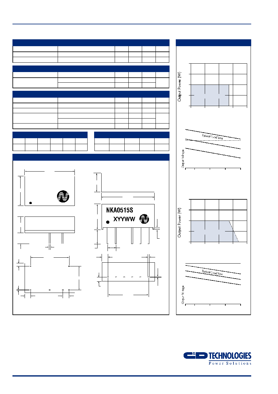
TEMPERATURE CHARACTERISTICS
Temperature Derating Graph
NKA0303D/S, 0305D/S, 0505DE/SE
types only
6 Pin SIP Package Style
14 Pin DIP Package Style
Ambient Temperature (∞C)
85∞C
120∞C
2.0
1.5
1.0
0.5
0
Safe Operating Area
-40
0
50
100
150
10
25
50
75
100
Output Load Current (%)
Tolerance Envelope
+
9%
+1%
V
NOM
≠7%
+1%
≠7%
≠15%
Temperature Derating Graph
All other types
Ambient Temperature (∞C)
85∞C
120∞C
2.0
1.5
1.0
0.5
0
Safe Operating Area
-40
0
50
100
150
10
25
50
75
100
Output Load Current (%)
Tolerance Envelope
+
10%
+5%
V
NOM
+2.5%
≠2.5%
≠7.5%
NKA0505D
XYYWW
PIN CONNECTIONS - 6 PIN SIP
1
V
IN
2
GND
4
-V
5
0V
6
+V
1
7
8
9
11
14
7.62
15.24
2.13
2.54
0.30
0.20
1.09