 | –≠–ª–µ–∫—Ç—Ä–æ–Ω–Ω—ã–π –∫–æ–º–ø–æ–Ω–µ–Ω—Ç: NNL10-4 | –°–∫–∞—á–∞—Ç—å:  PDF PDF  ZIP ZIP |
FEATURES
Industry Standard Footprint
Short Circuit Protection
High Efficiency
Under Voltage Lock Out
Output Voltage Trimming
Operating Temperature Range
≠40∞C to 85∞C
SMD Construction
Optional DC OK Signal
Options available without Trim and
Remote Sense Functionality
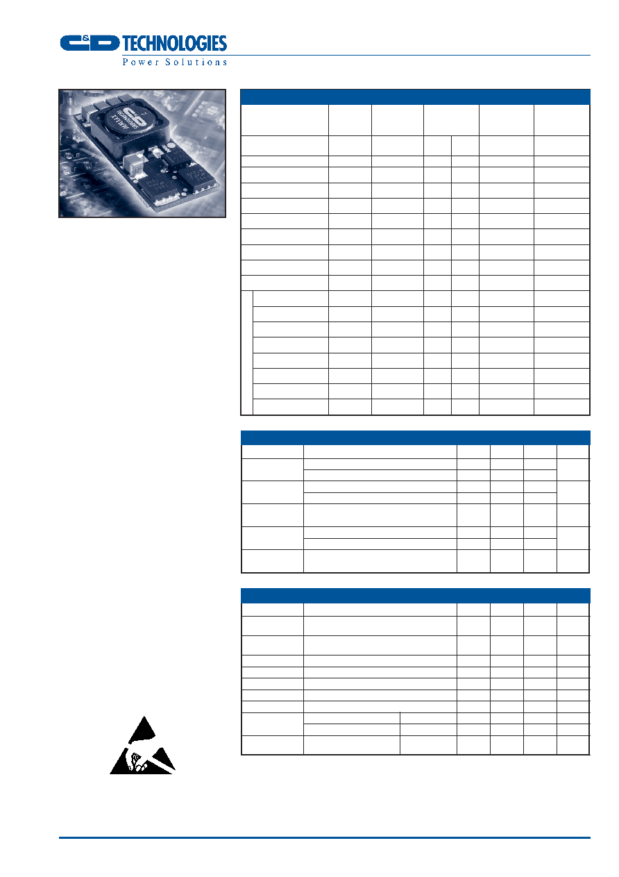
DESCRIPTION
The NNL10 series is part of a range of non-
isolated, cost effective DC/DC converters
offering high precision output voltages from a
nominal 3.0≠5.5 or 10.0≠14.0 intermediate
bus where isolation is not required. Available
in both SMD and SIP mechanical formats.
Parameter
Conditions
MIN
TYP
MAX
Units
V
NOM
= 4.0V
DC
V
OUT
< 2.75V
3.0
5.5
Voltage Range
V
NOM
= 4.0V
DC
V
OUT
> 3.0V
4.0
5.5
V
Under Voltage
Turn On Threshold V
NOM
= 4.0V
DC
2.8
Lock Out
Turn Off Threshold V
NOM
= 4.0V
DC
2.7
V
Reflected Ripple
30
mA p-p
Current
Input No Load
V
IN
= 5.5V V
OUT
= 0.9V
100
mA
Current
V
IN
= 5.5V V
OUT
= 3.3V
140
Input Standby
V
IN
= 5.5V Module Disabled
1.5
mA
Current
INPUT CHARACTERISTICS
1
OUTPUT CHARACTERISTICS
1
1 Specifications typical at T
A
=25∞C, nominal input voltage and rated output current unless otherwise specified.
Other customer specified options are available on request. Standard parts are supplied with Remote Sense and
Voltage Trim functions. Please contact your sales representative or C&D Technologies account manager for
further details.
NNL10 SERIES
Non-Isolated DC/DC Converters
Parameter
Conditions
MIN
TYP
MAX
Units
Rated Current
T
A
= ≠40∞C to 85∞C
10.0
A
(see thermal performance characteristics)
Voltage Set
1.0 2.0
%
Point Accuracy
Line Regulation Low line to high line
0.5
1.0
%
Load Regulation 0% load to 100% load
0.55
%
Ripple & Noise BW = DC to 20MHz
25
50
mVp-p
Voltage Trim
-10
+10
%V
OUT
Remote Sense
0.5
V
Transient
I
OUT
= 5.0A≠10.0A≠5.0A, Peak Deviation
100
mV
Response
C
OUT
= 1µF//10µF
Settling Time
70
µs
External Load
10,000
µF
Capaitance
www.cdpoweronline.com
SELECTION GUIDE
1
Nominal
Output
Output
MAX
Nominal
Input
Voltage
Current
Output
Efficiency
Voltage
Power
Min
Full
Min
Load
Load
Order Code
V
V
A
A
W
%
NNL10-1
4.0
0.9
0
10.0
9.0
79.7
NNL10-2
4.0
1.0
0
10.0
10.0
81.8
NNL10-3
4.0
1.2
0
10.0
12.0
84.3
NNL10-4
4.0
1.5
0
10.0
15.0
86.5
NNL10-5
4.0
1.8
0
10.0
18.0
88.2
NNL10-6
4.0
2.0
0
10.0
20.0
89.2
NNL10-7
4.0
2.5
0
10.0
25.0
91.2
NNL10-8
4.0
3.3
0
10.0
33.0
92.1
NNL10-9
4.0
0.9
0
10.0
9.0
79.7
NNL10-10
4.0
1.0
0
10.0
10.0
81.8
NNL10-11
4.0
1.2
0
10.0
12.0
84.3
NNL10-12
4.0
1.5
0
10.0
15.0
86.5
NNL10-13
4.0
1.8
0
10.0
18.0
88.2
NNL10-14
4.0
2.0
0
10.0
20.0
89.2
NNL10-15
4.0
2.5
0
10.0
25.0
91.2
NNL10-16
4.0
3.3
0
10.0
33.0
92.1
With DCOK
1
Short circuit protection
Continuous
Remote Sense
V
OUT
±0.5V
DC
DC OK
-0.2Vdc to +17V
DC
20mA
Remote ON/OFF
-0.2V
DC
to +17V
DC
Trim
-0.3V
DC
to V
OUT
Input Voltage V
IN
6.5V
DC
Minimum load
0%
ABSOLUTE MAXIMUM RATINGS
NNL10 SERIES
Non-Isolated DC/DC Converters
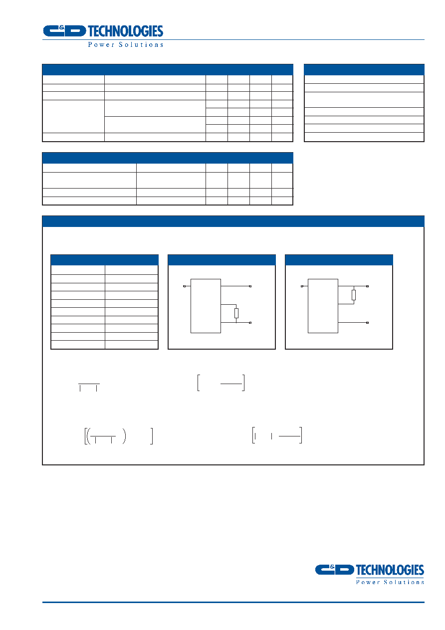
OUTPUT VOLTAGE TRIMMING
The trimming input on the NNL10 allows output voltage adjustment by +/-10% of nominal output voltage by
connection of a resistor or by application of a voltage to the Trim pin.
To increase the output voltage, an external resistor (Fig. 1) or voltage
source should be connected between the Trim pin and GND pin.
Vout is the required change in output voltage in V
To decrease the output voltage, an external resistor (Fig. 2) or voltage source should be connected between
the Trim pin and the V
OUT
pin.
The trim pin should be left disconnected if not used.
R
TRIM≠UP
=
24.080
≠ R
INTERNAL
K
V
OUT
V
TRIM≠UP
= 0.8 ≠
V
OUT
x R
INTERNAL
30.100
V
TRIM≠DOWN
= 0.8 + V
OUT
x
R
INTERNAL
30.100
V
OUT SET
R
INTERNAL
(V)
(kOhm)
0.9
5.1
1.0
30.1
1.2
59.0
1.5
100.0
1.8
100.0
2.0
100.0
2.5
78.7
3.3
59.0
R
INTERNAL
VALUES
FIG.1
R
TRIM
V
OUT
GND
TRIM
NNL10
V
IN
FIG.2
V
OUT
GND
TRIM
NNL10
V
IN
R
TRIM≠DOWN
=
V
OUT
≠0.8
≠1 x 30.100 ≠ R
INTERNAL
K
V
OUT
R
TRIM
2
ENVIRONMENTAL
1
Parameter
Conditions
MIN
TYP
MAX
Units
Operation
See thermal performance
≠40
85
∞C
characteristics
Over Temperature Protection
Substrate temperature
115
∞C
Storage
≠55
125
∞C
GENERAL CHARACTERISTICS
1
Parameter
Conditions
MIN
TYP
MAX
Units
Switching Frequency
300
kHz
Start Delay
From power on/remote off
4.0
ms
Module On (or pin unconnected)
0
0.3
V
Remote On/Off
100
µA
Module Off
2.6
V
-500
µA
MTTF
TBA
kHrs
NNL10 SERIES
Non-Isolated DC/DC Converters
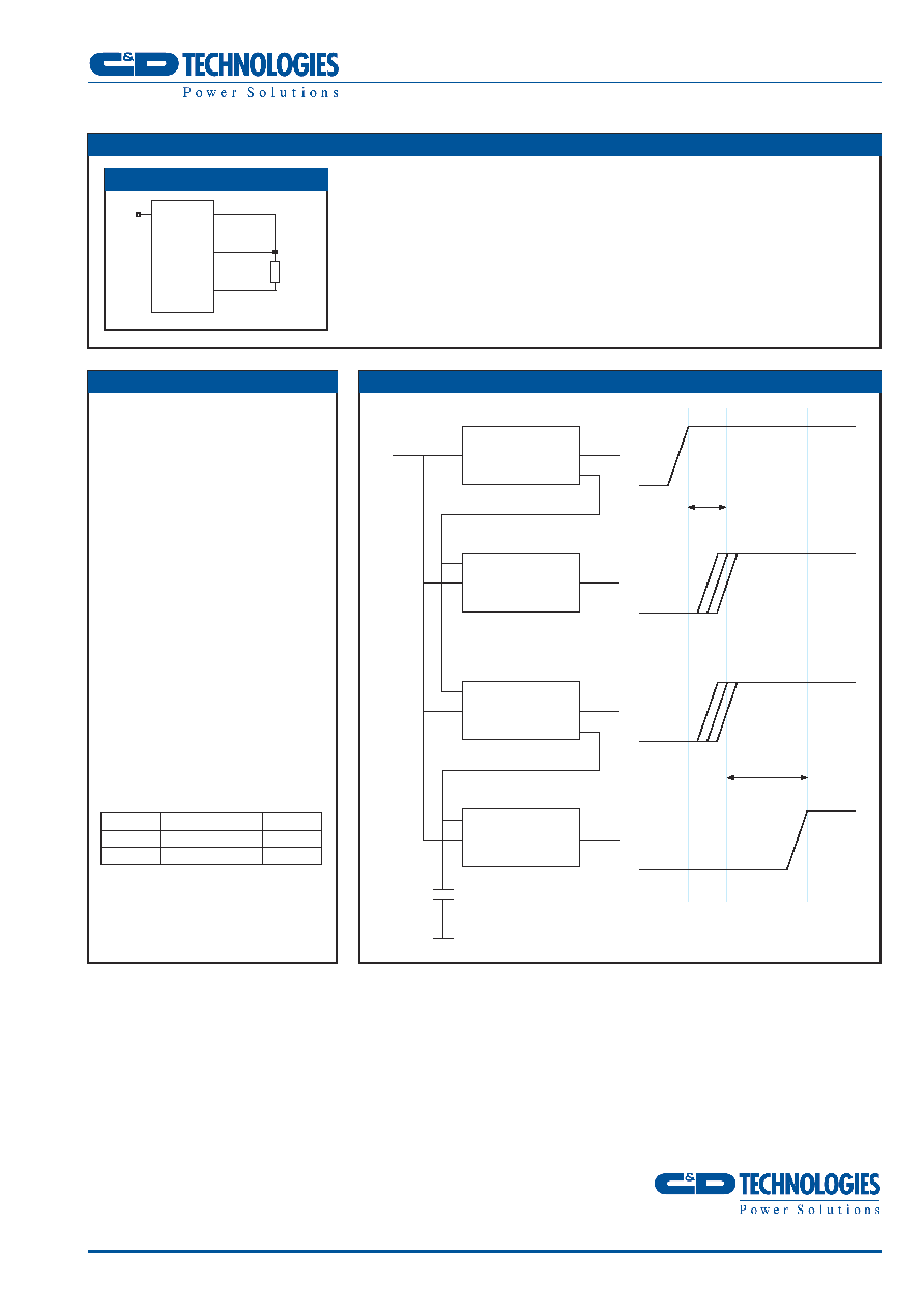
REMOTE SENSE
The remote sense function compensates for voltage drops from the
output of the NNL10 to the load point by regulating the output volt-
age at the load point. The voltage drop must not exceed 0.5V,
although Trim and remote sense functions can be used in combina-
tion with each other, the maximum voltage increase is 0.5V.
When increasing the output voltage the maximum output power of
the NNL10 must not exceed the maximum output figures stated in
the selection guide.
OUTPUT SEQUENCING
To simplify output sequencing, the
NNL10 series offers an optional single
wire interconnection that performs this
function. Using this connection, up to
four devices can be 'daisy chained'
together, with the 'DC OK' signal from
one converter signifying that the next
converter can be enabled. A
capacitor, simply connected to the
daisy chain link, provides a settable
delay in the sequence of the
converters starting.
Typical capacitor values and
corresponding delays are shown in
the table below.
Figure 4 shows a typical sequencing
configuration, along with the voltage
outputs that it produces. As well as
reducing component count, making
use of the 'built-in' sequencing
capability means that only a single
PCB track is required for a full
sequencing solution.
ON/OFF
ON/OFF
ON/OFF
DC OK
V
IN
DC OK
Bus Voltage
T
PRESET
+ T
CAP
T
PRESET
Capacitor
V
OUT 1
V
OUT 2
V
OUT 3
V
OUT 4
V
IN
V
IN
V
IN
V
OUT 1
V
OUT 2
V
OUT 3
V
OUT 4
FIG.4
FIG.3
V
OUT
GND
SENSE
LOAD
NNL10
V
IN
3
V
IN
Capacitor Value
Delay
3.0V
DC
0.22µF
1.8mS
5.5V
DC
0.22µF
0.6mS
4
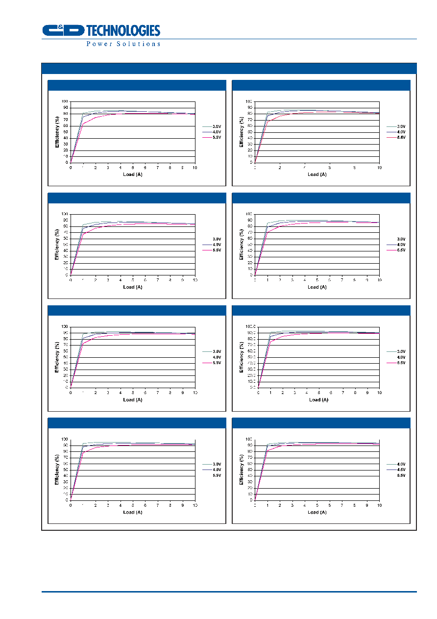
NNL10 SERIES
Non-Isolated DC/DC Converters
EFFICIENCY v LOAD GRAPHS (NNL10 V
NOM
= 4.0V
DC
)
V
OUT
= 0.9V
V
OUT
= 1.0V
V
OUT
= 1.2V
V
OUT
= 1.5V
V
OUT
= 1.8V
V
OUT
= 2.0V
V
OUT
= 2.5V
V
OUT
= 3.3V

5
NNL10 SERIES
Non-Isolated DC/DC Converters
THERMAL DERATING GRAPHS (NNL10 V
NOM
= 4.0V
DC
)
V
OUT
= 0.9V
V
OUT
= 1.0V
V
OUT
= 1.2V
V
OUT
= 1.5V
V
OUT
= 1.8V
V
OUT
= 2.0V
V
OUT
= 2.5V
V
OUT
= 3.3V
6
NNL10 SERIES
Non-Isolated DC/DC Converters
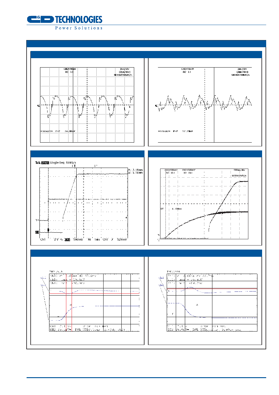
V
IN
= 4.75V
DC
V
OUT
= 3.3V
DC
I
OUT
= 10.0A
TYPICAL CHARACTERISTICS
V
IN
= 4.0V
DC
V
OUT
= 0.9V
DC
I
OUT
= 10.0A
START-UP FROM APPLICATION OF V
IN
START-UP USING REMOTE ON/OFF
Response when remote on/off driven from an open collector output.
V
IN
= 4.0V
DC
V
OUT
= 3.3V
DC
I
OUT
Change = 50-100%
V
IN
= 4.0V
DC
V
OUT
= 3.3V
DC
I
OUT
Change = 100-50%
OUTPUT RIPPLE & NOISE
TRANSIENT RESPONSE

NNL10 SERIES
Non-Isolated DC/DC Converters
PIN CONNECTIONS
Pin Number
1
2
3
4
5
6
7
ON/OFF
V
IN
DC OK*
GND
V
OUT
TRIM
SENSE
C&D Technologies (NCL) Ltd
Tanners Drive, Blakelands North
Milton Keynes MK14 5BU, England
Tel: +44 (0)1908 615232
Fax: +44 (0)1908 617545
email: info@cdtechno-ncl.com
www.cdpoweronline.com
C&D Technologies Inc.
3400 E Britannia Drive, Tucson,
Arizona 85706, USA
Tel: +1 (800) 547-2537
Fax: +1 (520) 741-4598
email: sales@cdtechno.com
C&D Technologies Inc. reserve the right to alter or improve the specification,
internal design or manufacturing process at any time, without notice. Please
check with your supplier or visit our web site to ensure that you have the
current and complete specification for your product before use.
© C&D Technologies Inc. 2004
NDC NNL10.2
No part of this publication may be copied, transmitted or stored in a
retrieval system or reproduced in any way including, but not limited to,
photography, photocopy, magnetic or other recording means, without prior
written permission from C&D Technologies Inc.
Instructions for use are available from: www.cdpoweronline.com
Unless otherwise stated all dimensions in inches(mm) ±0.01(0.25).
Weight: 5.7g
* Pin 6 (DC OK) is an optional feature which allows multiple NNL10 DC/DC Converters to have sequenced outputs
when used in conjunction with the Remote ON/OFF pin (see application note for further information).
1.3 (33.0)
MECHANICAL DIMENSIONS
SMD Package Style Bottom View
1
2
3
4
5
6
7
0.19
(4.83)
0.297
(7.54)
0.326
(8.28)
MAX
0.062
(1.58)
0.19
(4.83)
0.19
(4.83)
0.19
(4.83)
0.12
(3.04)
0.405
(10.29)
0.112 (2.84)
0.062
(1.57)
0.075 (1.91)
0.530
(13.46)
7
0.048 (1.22)
PACKAGING
12.40(315.00)
Unless otherwise stated all dimensions in inches(mm) ± 0.014(0.35).
1.614(41.0)
1.102
(28.0)
5.354
(136.0)
0.709(18.0)
Tray quantity: 28
+0.020(0.5)
-- 0.00(0.0)
Tray Dimensions (top view)
Pick up location (top view)
0.476(12.08)
0.265(6.73)