 | –≠–ª–µ–∫—Ç—Ä–æ–Ω–Ω—ã–π –∫–æ–º–ø–æ–Ω–µ–Ω—Ç: PWR1312 | –°–∫–∞—á–∞—Ç—å:  PDF PDF  ZIP ZIP |
PWR13XX 4/2002 REV G
Page 1
Product Data Sheet
1.5 W
ATTS
U
NREGULATED
DC/DC C
ONVERTERS
Website: http://www.cdpowerelectronics.com
Power Electronics Division, United States
3400 E Britannia Drive, Tucson, Arizona 85706
Phone: 520.295.4100 Fax: 520.295.4197
PWR13XX
FEATURES
HIGH ISOLATION - 4000V RATING
8000V ISOLATION TEST VOLTAGE
BARRIER 100% PRODUCTION TESTED
LOW BARRIER CAPACITANCE - 10PF
LOW LEAKAGE CURRENT - 2µA MAX
24-PIN DIP PACKAGE
INTERNAL FILTERING
APPLICATIONS
BIOMEDICAL DATA ACQUISITION
INDUSTRIAL PROCESS CONTROL
ANALYTICAL MEASUREMENTS
GROUND LOOP ELIMINATION
INTRINSIC SAFETY SYSTEMS
DESCRIPTION
The PWR13XX Series offers a broad line of low-cost,
high-isolation voltage, unregulated, single and dual output
DC/DC converters in a 24-pin DIP package. These small
converters offer a 4000V isolation rating in a 1.25" x 0.8"
package area.
The dielectric withstand characteristics of each converter
is tested in production to ensure barrier integrity. During the
development of the PWR13XX Series extensive testing
was done to verify that subjecting the barrier to as many
as ten barrier tests will not destroy the barrier.
The PWR13XX Series uses advanced circuit design and
packaging technology to realize superior reliability and
performance. A 220kHz driven push-pull oscillator is used
to ensure stable frequency and non-saturating operation
of the input stage. This means there are no high peak
voltages or currents like other design topologies, which
can reduce unit reliability. Reliability is further enhanced
by the use of MOSPOWER transistors. These rugged
devices permit higher frequency operation with less
complicated drive circuitry than is possible with bipolar
power transistors. Reduced parts count adds to the reliability
of the PWR13XX Series.
The high efficiency of the PWR13XX Series means less
internal power dissipation. With less heat to dissipate,
the PWR13XX Series can operate over a wider ambient
temperature range with no degradation of reliable operation.
The PWR13XX Series offers the user low cost without
sacrificing reliability. The use of surface mounted devices
and manufacturing technologies make it possible to offer
premium performance and low cost. Testing of the
PWR13XX isolation barrier is performed per the methods
set forth by UL544, VDE750, CSA 22.2 and IEC 601-1.
C&D Technologies, (NCL)
Milton Keynes MK14 5BU UK
Tel: +44 (0)1908 615232 Fax: +44 (0)1908 617545
PWR13XX 4/2002 REV G
Page 2
NOMINAL
RATED
RATED
REFLECTED
INPUT VOLTAGE
OUTPUT VOLTAGE
OUTPUT CURRENT
NO LOAD
RATED LOAD
RIPPLE CURRENT
MODEL
(V
DC
)
(V
DC
)
(mA)
(mA)
(mA)
(mAp-p)
PWR1300
5
5
300
50
400
30
PWR1301
5
12
125
50
400
30
PWR1302
5
15
100
50
400
30
PWR1303
5
± 5
±150
50
400
30
PWR1304
5
±12
±63
50
400
30
PWR1305
5
±15
±50
50
400
30
PWR1306
12
5
300
30
167
25
PWR1307
12
12
125
30
167
25
PWR1308
12
15
100
30
167
25
PWR1309
12
± 5
±150
30
167
25
PWR1310
12
±12
±63
30
167
25
PWR1311
12
±15
±50
30
167
25
PWR1312
15
5
300
30
133
20
PWR1313
15
12
125
30
133
20
PWR1314
15
15
100
30
133
20
PWR1315
15
± 5
±150
30
133
20
PWR1316
15
±12
±63
30
133
20
PWR1317
15
±15
±50
30
133
20
INPUT
Voltage Range
4.5
5
5.5
V
DC
10.8
12
13.2
V
DC
13.5
15
16.5
V
DC
ISOLATION
Rated Voltage
4,000
V
DC
Test Voltage
60 Hz, 60 Seconds
8,000
Vpk
Resistance
10
G
Capacitance
10
pF
Leakage Current
V
ISO
= 240VAC, 60Hz
1
2
µArms
OUTPUT
Rated Power
1.5
Watts
Voltage Setpoint Accuracy
Rated Load, Nominal V
in
±5
%
Ripple & Noise
BW = DC to 10MHz
40
mVp-p
BW = 10Hz to 2MHz
10
mVrms
REGULATION
Line Regulation
High Line to Low Line
1.5
%/%
Load Regulation
See Performance Curves
GENERAL
Efficiency
75
%
Switching Frequency
220
kHz
Package Weight
12
g
MTTF per MIL-HDBK-217, Rev. E
Circuit Stress Method
Ground Benign
T
A
= +25∞C
2,000,000
Hr
T
A
= +85∞C
90,000
Hr
Fixed Ground
T
A
= +35∞C
540,000
Hr
Naval Sheltered
T
A
= +35∞C
300,000
Hr
Airborne Uninhabited Fighter
T
A
= +35∞C
55,000
Hr
TEMPERATURE
Specification
-40
+25
+85
∞C
Operation
-55
+100
∞C
Storage
-55
+110
∞C
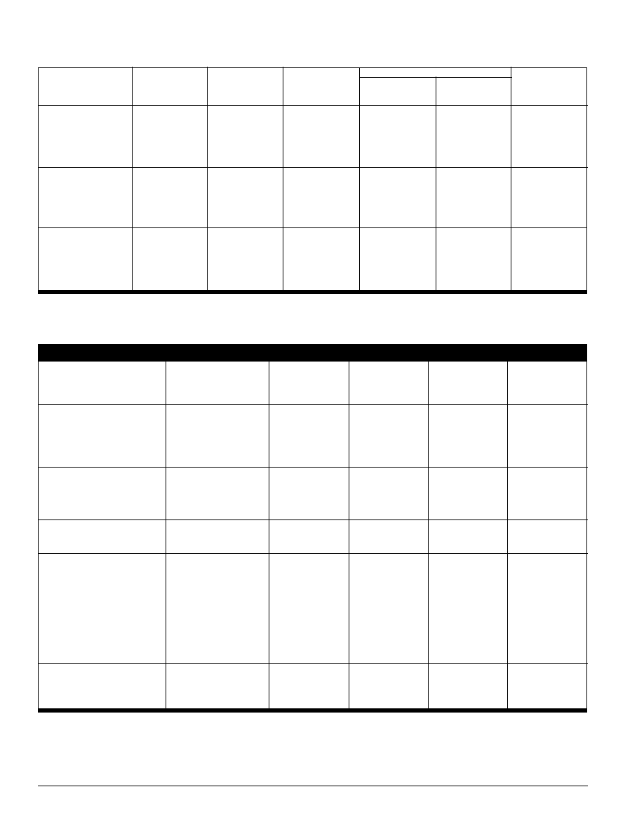
ELECTRICAL SPECIFICATIONS
Specifications typical at T
A
= +25∞C, nominal input voltage, rated output current unless otherwise noted.
INPUT CURRENT
COMMON SPECIFICATIONS
Specifications typical at T
A
= +25∞C, rated input voltage, rated output current unless otherwise noted.
PARAMETER
CONDITIONS
MIN
TYP
MAX
UNITS
PWR13XX 4/2002 REV G
Page 3
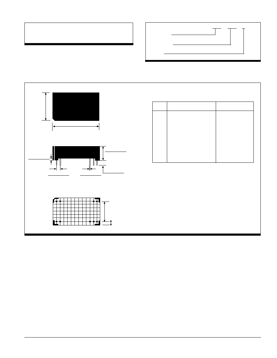
MECHANICAL
ABSOLUTE MAXIMUM RATINGS
Output Short-Circuit Duration ..................................................... 5 seconds
Internal Power Dissipation .............................................................. 750mW
Lead Temperature (soldering, 10 seconds max) ............................ +300∞C
Device Family
PWR indicates DC/DC converter
Model Number
Selected from Table of Electrical Characteristics
Package
PWR
13XX
A
ORDERING INFORMATION
Notes:
All dimensions are in inches (millimeters).
GRID: 0.100 inches (2.54 millimeters)
*
Common pins not present on single output models.
PIN PLACEMENT TOLERANCE: ± 0.015"
Marked with: specific model ordered, date code, job code.
MATERIAL: Units are encapsulated in a low thermal resistance
molding compound which has excellent chemical resistance, wide
operating temperature range, and good electrical properties under
high humidity environments. The encapsulant and outer shell of the
unit have UL94V-0 ratings. Lead material is brass with a solder
plated surface to allow ease of solderability.
PIN CONNECTIONS
PIN
SINGLE MODELS
DUAL MODELS
1
+V
IN
+V
IN
2
+V
IN
+V
IN
11
+V
OUT
+V
OUT
12
+V
OUT
+V
OUT
13
-V
OUT
Common
14
-V
OUT
Common
15
No Pin
-V
OUT
23
-V
IN
-V
IN
24
-V
IN
-V
IN
1.270±0.010"
(32.26)
.805±0.010"
(20.45)
.010±0.005"
(0.25)
0.400±0.010"
(10.16)
0.170" MIN
(4.32)
0.100±0.015"
(2.54)
.020±0.002"
(0.51)
12
11
2
1
13
14
15
23
24
BOTTOM VIEW
SIDE VIEW
TOP VIEW
0.600"
(15.23)
.1025"
(.267)

PWR13XX 4/2002 REV G
Page 4
TYPICAL PERFORMANCE CURVES
Specifications at T
A
= +25
∞
C, nominal input voltage, rated output current
16.00
15.75
15.50
15.25
15.0
14.00
13.50
13.00
12.50
12.00
0 25% 50% 75% 100%
0 25% 50% 75% 100%
0 25% 50% 75% 100%
5.8
5.6
5.4
5.2
5.0
Load (% of Rated)
Load (% of Rated)
Load (% of Rated)
0 25% 50% 75%
100%
Load (% of Rated)
Load (% of Rated)
14.00
13.50
13.00
12.50
12.0
0 25% 50% 75% 100%
16.00
15.75
15.50
15.25
15.0
0 25% 50% 75% 100%
5.8
5.6
5.4
5.2
5.0
V
OUT
VS LOAD
(5VOUT MODELS)
V
OUT
VS LOAD
(12VOUT MODELS)
V
OUT
VS LOAD
(15VOUT MODELS)
V
OUT
VS LOAD
(±15VOUT MODELS)
Load (% of Rated)
V
OUT
VS LOAD
(±5VOUT MODELS)
V
OUT
(VDC)
V
OUT
(VDC)
V
OUT
(VDC)
V
OUT
(VDC)
V
OUT
(VDC)
V
OUT
(VDC)
V
OUT
VS LOAD
(±12VOUT MODELS)
Any data, prices, descriptions or specifications presented herein are subject to revision by C&D Technologies, Inc. without notice. While such information is believed to
be accurate as indicated herein, C&D Technologies, Inc. makes no warranty and hereby disclaims all warranties, express or implied, with regard to the accuracy or
completeness of such information. Further, because the product(s) featured herein may be used under conditions beyond its control, C&D Technologies, Inc. hereby
disclaims all warranties, either express or implied, concerning the fitness or suitability of such product(s) for any particular use or in any specific application or arising from
any course of dealing or usage of trade. The user is solely responsible for determining the suitability of the product(s) featured herein for user's intended purpose and
in user's specific application. C&D Technologies, Inc. does not warrant or recommend that any of its products be used in any life support or aviation or aerospace
applications.