
PWR40XX 5/2001 REV E
Page 1
FEATURES
LOW COST
INDUSTRY-STANDARD PACKAGE
SINGLE AND DUAL OUTPUTS
INTERNAL INPUT AND OUTPUT FILTERING
HIGH ISOLATION VOLTAGE OPTION AVAILABLE
DESCRIPTION
The PWR40XX Series offers a low-cost alternative for some
of the most popular DC/DC converters industry wide. Each
model has a high-isolation version and an outstanding
demonstrated MTTF of 5,000,000 hours at 25∞C. The superior
reliability and low cost make it an excellent choice for industry
standard usages.
The series includes thirteen standard models (other input
and output voltages are available upon request), all set in a
flexible encapsulation material which has excellent thermal
dissipation and low mechanical stress on internal components.
The use of surface-mount devices and manufacturing
processes, combined with the encapsulation process, provides
the user a product that is environmentally rugged.
The PWR40XX has full isolation between input and output to
give the designer maximum flexibility in grounding options
and polarity configurations. The outputs are protected against
momentary short circuits.
Notes:
All dimensions are in inches (millimeters).
GRID: 0.100 inches (2.54 millimeters)
*
Common pins not present on single output models.
PIN PLACEMENT TOLERANCE: ± 0.015"
Marked with: specific model ordered, date code, job code.
MECHANICAL
MATERIAL: Units are encapsulated in a low thermal resistance
molding compound which has excellent chemical resistance, wide
operating temperature range, and good electrical properties under
high humidity environments. The encapsulant and outer shell of
the unit have UL94V-0 ratings. Lead material is brass with a solder
plated surface to allow ease of solderability.
PIN #
FUNCTION
1
+V
IN
2
≠V
IN
3
+V
OUT
4
* Common
5
≠V
out
TOP VIEW
SIDE VIEW
BOTTOM VIEW
PWR40XX
POWER ELECTRONICS DIVISION
SERIES DC/DC CONVERTER
PRODUCT DATA SHEET
PWR40XX
PWR40XX
POWER: 4 Watt
LOW COST UNREGULATED
SIZE: 1.125" X 1.125" X 0.40"
www.cdtechno.com
click on Power Electronics

PWR40XX 5/2001 REV E
Page 2
ELECTRICAL SPECIFICATIONS
Specifications typical at T
A
= +25∞C, nominal input voltage and rated output current unless otherwise specified.
MINIMUM
NOMINAL
MAXIMUM
RATED
RATED
REFLECTED
INPUT
INPUT
INPUT
OUTPUT
OUTPUT
NO
RATED
RIPPLE
VOLTAGE
VOLTAGE
VOLTAGE
VOLTAGE
CURRENT
LOAD
LOAD
CURRENT
MODEL
(V
DC
)
(V
DC
)
(V
DC
)
(V
DC
)
(mA)
(mA)
(mA)
(mAp-p)
PWR4000
4.5
5
5.5
5
800
50
950
20
PWR4004
4.5
5
5.5
±12
±170
50
950
20
PWR4005
4.5
5
5.5
±15
±135
50
950
20
PWR4006
10.2
12
13.8
5
800
35
400
30
PWR4007
10.2
12
13.8
12
340
35
400
30
PWR4010
10.2
12
13.8
±12
±170
35
400
30
PWR4011
10.2
12
13.8
±15
±135
35
400
40
PWR4012
12.75
15
17.25
5
800
30
300
40
PWR4016
12.75
15
17.25
±12
±170
30
300
40
PWR4017
12.75
15
17.25
±15
±135
30
300
40
PWR4018
20.40
24
27.6
5
800
30
180
40
PWR4022
20.40
24
27.6
±12
±170
30
180
40
PWR4023
20.40
24
27.6
±15
±135
30
180
40
Other input and output voltage options may be available. Please contact factory.
INPUT CURRENT
COMMON SPECIFICATIONS
Specifications typical at T
A
= +25∞C, nominal input voltage and rated output current unless otherwise specified.
PARAMETER
CONDITIONS
MIN
TYP
MAX
UNITS
ISOLATION (Standard)
Rated Voltage
500
V
DC
Test Voltage
60Hz, 10 seconds
500
Vpk
Resistance
10
GW
Capacitance
50
pF
Leakage Current
V
ISO
= 240VAC, 60Hz
5
µArms
ISOLATION (≠HV Option)
Rated Voltage
1000
V
DC
Test Voltage
60Hz, 60 seconds
3000
Vpk
Resistance
10
G
Capacitance
50
pF
Leakage Current
V
ISO
= 240V
AC
, 60Hz
5
15
µArms
OUTPUT
Rated Power
4.0
W
Voltage Setpoint Accuracy
Rated Load, Nominal V
IN
±3
+7, -5
%
Temperature Coefficient
±0.02
%/∞C
Ripple & Noise
BW = DC to 10MHz
140
mVp-p
BW = 10Hz to 20MHz
10
mVrms
Voltage
No Load, V
OUT
= + 5V
7
V
DC
No Load, V
OUT
= ±12V
±15
V
DC
No Load, V
OUT
= ±15V
±18
V
DC
Line Regulation
1.0
%/%V
IN
Load Regulation
See Curves
GENERAL
Switching Frequency
170
kHz
Package Weight
16
g
MTTF per MIL-HDBK-217 Rev. E *
Circuit Stress Method
5,000,000
Hr
Efficiency
80
%
TEMPERATURE
Specification
0
+25
+70
∞C
Operation
≠25
+85
∞C
Storage
≠40
+100
∞C
PWR40XX 5/2001 REV E
Page 3
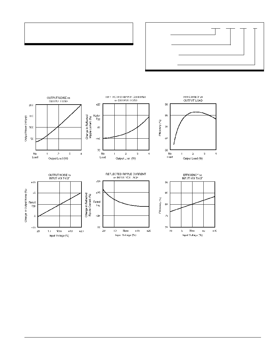
TYPICAL PERFORMANCE CURVES
T
A
= +25∞C, Rated Input Voltage, rated Output Current unless otherwise noted.
ABSOLUTE MAXIMUM RATINGS
Output Short-Circuit Duration ...................................................... 1 second
Internal Power Dissipation .............................................................. 850mW
Lead Temperature (soldering, 10 seconds max) ............................ +300∞C
Device Family
PWR indicates DC/DC converter
Model Number
Selected from Table of Electrical Characteristics
High Voltage Option
No Designator Indicates Standard Model
Optional Screening
PWR
40XX
-HV /H
ORDERING INFORMATION

PWR40XX 5/2001 REV E
Page 4
OUTPUT POWER
The PWR40XX series was designed to meet power require-
ments up to 4W. Due to the nature of unregulated power
supplies, a higher-than-rated output voltage will result when
less-than-rated power is used (see Typical Performance
Curves). This series has been designed to run from no load
to 4W without derating up to +70∞C.
UNBALANCED LOADS
Unbalanced loads may be used on dual output models with
each side sourcing up to 200mA as long as the total power
out is not more than 4W. With an unbalanced load, the output
voltages will track within 5% of each other.
OUTPUT NOISE
The output noise can be reduced to less than 50mVp-p by
adding a low ESR 10µf tantalum capacitor across each
output.
TYPICAL PERFORMANCE CURVES
T
A
= +25
∞
C, rated input voltage, rated output current unless otherwise noted.
APPLICATION NOTES
SHORT CIRCUIT PROTECTION
To maintain low cost, the PWR40XX Series provides limited
short-circuit protection. To protect against continuous short
circuits, a fuse is required. It is recommended that the fuse
be placed in series with the input of the converter. The
required I
2
t will vary with input voltage.
Input Voltage
Littlefuse
©
Part Number
5V
229.015
12V
229.500
15V
229.375
24V
229.250
TABLE I. Recommended Fuses (or Equivalent).
Any data, prices, descriptions or specifications presented herein are subject to revision by C&D Technologies, Inc. without notice. While such information is believed to be accurate as indicated herein, C&D
Technologies, Inc. makes no warranty and hereby disclaims all warranties, express or implied, with regard to the accuracy or completeness of such information. Further, because the product(s) featured herein
may be used under conditions beyond its control, C&D Technologies, Inc. hereby disclaims all warranties, either express or implied, concerning the fitness or suitability of such product(s) for any particular use or
in any specific application or arising from any course of dealing or usage of trade. The user is solely responsible for determining the suitability of the product(s) featured herein for user's intended purpose and in
user's specific application. C&D Technologies, Inc. does not warrant or recommend that any of its products be used in any life support or aviation or aerospace applications.
Power Electronics Division, United States
3400 E Britannia Drive, Tucson, Arizona 85706
Phone: 800.547.2537
Fax: 520.770.9369
Power Electronics Division, Europe
C&D Technologies (Power Electronics) Ltd.
132 Shannon Industrial Estate
,
Shannon, Co. Clare, Ireland
Tel: +353.61.474.133
Fax:+353.61.474.141
C&D Technologies, (NCL)
Tanners Drive Blakelands North
Milton Keynes MK14 5BU UK
Tel: +44 (0)1908 615232
Fax: +44 (0)1908 617545