PWR60XX 6/99 REV D
Page 1
FEATURES
G
G
G
G
G Low Cost
G
G
G
G
G Low Noise
G
G
G
G
G Industry-Standard Package
G
G
G
G
G Single and Dual Outputs
G
G
G
G
G High Isolation Voltage Option Available
G
G
G
G
G Linear Output Regulation
G
G
G
G
G Internal Input and Output Filtering
G
G
G
G
G Low EMI Transformer Design
G
G
G
G
G No External Components Required
G
G
G
G
G Thermal Shutdown Protection
DESCRIPTION
The PWR60XX Series offers a low-cost alternative for some
of the most popular DC/DC converters industry wide. Each
model has very low noise and an outstanding MTTF. The
superior reliability, excellent filtering, and low cost make it an
excellent choice for industry-standard usage.
The series includes eleven models (other input and output
voltages are available upon request), all set in an encapsulant for
excellent thermal dissipation for internal components. The use
of surface-mount devices and manufacturing processes com-
bined with the encapsulation process, provides the user a
product that is more environmentally rugged.
The PWR60XX has full isolation between input and output to
give the designer maximum flexibility in grounding options and
polarity configurations. The outputs are protected against shorts
to increase the units survivability in harsh environments.
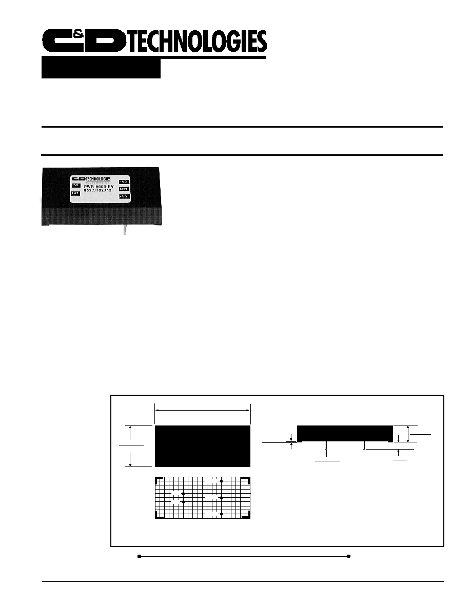
MECHANICAL
TOP VIEW
SIDE VIEW
NOTES: All dimensions are in inches (millimeters).
GRID: 0.100 inches (2.54 millimeters)
PIN PLACEMENT TOLERANCE: ±0.015
*
Common pins are not present on single output models.
Product marked with specific model ordered, date code, job code.
MATERIAL: Units are encapsulated in a low thermal resistance
molding compound which has excellent chemical resistance, wide
operating temperature range, and good electrical properties under
high humidity environments. The encapsulant and the outer shell
of the unit have UL94V-0 ratings. Lead material is brass with a
solder plated surface to allow ease of solderability.
2.000±0.015"
(50.80±0.38)
1.000±0.015"
(25.4±0.38)
0.015±.005"
(0.38)
0.170"
(4.32)
0.400±0.10"
(10.16)
Min.
0.040±0.003"
(1.02±0.08)
-V
IN
+
V
IN
+V
OUT
-V
OUT
*
COM
BOTTOM VIEW
Internet: http://www.cdpowerelectronics.com
Power Electronics Division, United States
3400 E Britannia Drive, Tucson, Arizona 85706
Phone: 800.547.2537 Fax: 520.770.9369
Power Electronics Division, Europe
C&D Technologies (Power Electronics) Ltd.
132 Shannon Industrial Estate, Shannon, Co. Clare, Ireland
Tel: +353.61.474.133 Fax:+353.61.474.141
1.8 W
ATT
R
EGULATED
DC/DC C
ONVERTER
Product Data Sheet
PWR60XX
PWR60XX 6/99 REV D
Page 2
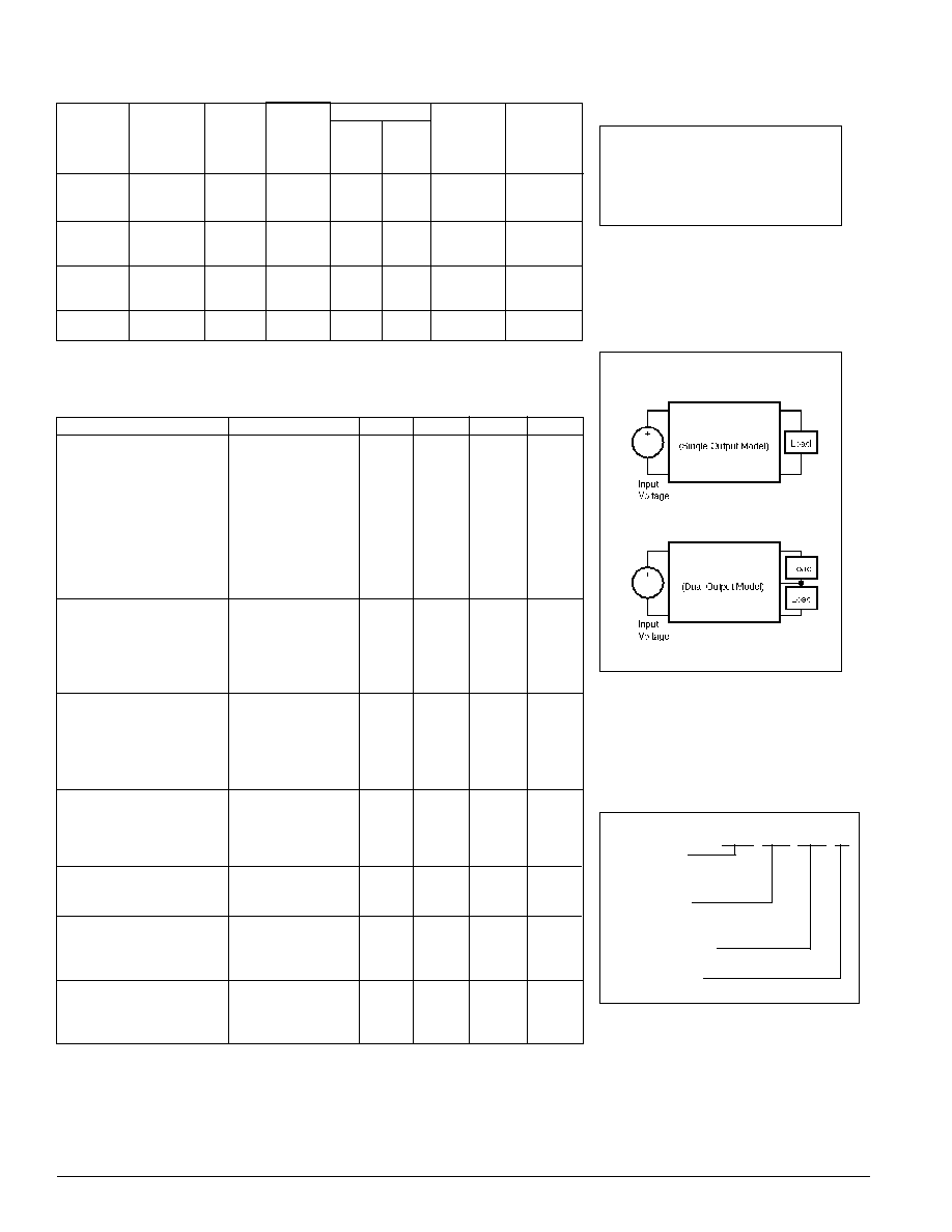
ELECTRICAL SPECIFICATIONS
Specifications typical at T
A
= +25∞C, rated input voltage, rated output current unless otherwise specified.
NOMINAL
RATED
RATED INPUT CURRENT
REFLECTED
INPUT
OUTPUT
OUTPUT
NO
RATED
RIPPLE
VOLTAGE
VOLTAGE
CURRENT
LOAD
LOAD
CURRENT
EFFICIENCY
MODEL
(V
DC
)
(V
DC
)
(mA)
(mA)
(mA)
(mAp-p)
(%)
PWR6000
5
5
360
70
655
15
55
PWR6004
5
±12
±75
70
570
15
63
PWR6005
5
±15
±60
70
555
15
65
PWR6006
12
5
360
30
275
10
55
PWR6010
12
±12
±75
30
240
10
63
PWR6011
12
±15
±60
30
230
10
65
PWR6012
15
5
360
25
220
8
55
PWR6016
15
±12
±75
25
190
8
63
PWR6017
15
±15
±60
25
185
8
65
PWR6018
24
5
360
13
120
12
62
PWR6023
24
±15
±60
13
120
12
62
NOTE: Other input to output voltages may be available. Please consult factory.
ABSOLUTE MAXIMUM RATINGS
Output Short-Circuit Duration
Outputs to Common .................. Continuous
Output to Output ....................... Momentary
Output Power ......................................... 2.0W
Lead Temperature .............................. +300∞C
(soldering, 10 seconds max)
TYPICAL APPLICATIONS
PWR 60XX ≠HV /H
Device Family
PWR Indicates
DC/DC converter
Model Number
Selected From Table of Electrical
Characteristics
High Voltage Option
No Designator Indicates Standard Model
Screening Option
ORDERING INFORMATION
COMMON SPECIFICATIONS
Specifications typical at T
A
= +25∞C, rated input voltage, rated output current unless otherwise specified.
PARAMETER
CONDITIONS
MIN
TYP
MAX
UNITS
INPUT
PWR6000
4.65
5.0
5.5
V
DC
PWR6004
4.65
5.0
5.5
V
DC
PWR6005
4.65
5.0
5.5
V
DC
PWR6006
10.9
12.0
13.2
V
DC
PWR6010
10.9
12.0
13.2
V
DC
PWR6011
10.9
12.0
13.2
V
DC
PWR6012
13.9
15.0
16.5
V
DC
PWR6016
13.9
15.0
16.5
V
DC
PWR6017
13.9
15.0
16.5
V
DC
PWR6018
21.6
24
26.4
V
DC
PWR6023
21.6
24
26.4
V
DC
ISOLATION (Standard)
Rated Voltage
500
V
DC
Test Voltage
500
Vpk
Resistance
10
G
Capacitance
27
pF
Leakage Current
V
ISO
=
240V
AC
, 60Hz
5
µArms
ISOLATION (≠HV Option)
Rated Voltage
1000
V
DC
Test Voltage
3000
Vpk
Resistance
10
G
Capacitance
27
pF
Leakage Current
V
ISO
=
240V
AC
, 60Hz
5
µArms
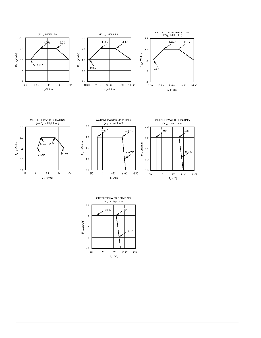
OUTPUT
Rated Power
≠25∞C - T
A
- +70∞C
1.8
Watts
Voltage Setpoint Accuracy
Rated Load, Nominal Vin
±2
%
Temperature Coefficient
±0.01
%/∞C
Ripple and Noise
BW =
DC
to 10MHz
20
45
mVp-p
REGULATION
Line
High Line to Low Line
±0.2
±1.0
%
Load
Full Load to No Load
0.5
1.0
%
GENERAL
Switching Frequency
150
kHz
Package Weight
20
g
MTTF per MIL-HDBK-217, RevE
Circuit Stress Method
930,000
Hr
TEMPERATURE
Specification
≠25
+25
+70
∞C
Operation
≠25
+100
∞C
Storage
≠40
+110
∞C