PWR72 5/99 REV B
Page 1
FEATURES
Low Price
High Power Output: 3 Watts
Wide Input Voltage Range: 5V
DC
To 22V
DC
Isolation Barrier 100% Tested Per UL544, VDE750,
and CSA C22.2 Dielectric Withstand
Isolation Barrier Leakage Current 100% Tested At
240V
AC
: 3µA Max
Low Isolation Barrier Capacitance: 10pF
Single-Channel; Dual Output
Six-Sided Shielding
DESCRIPTION
The PWR72 is a 3W, single-channel, dual-output DC/DC
converter designed for low cost spot power conversion and
ground elimination applications.
It provides a plus and minus output voltage approximately
equal to the input voltage magnitude. The PWR72 operates
over a wide range of input voltages from 5V
DC
to 22V
DC
. Its
unregulated outputs give the PWR72 high efficiency power
conversion.
Surface-mounted devices and manufacturing processes are
used in the PWR72 to give the user a device which is more
environmentally rugged than most DC/DC converters. The use
of surface-mounted technologies also gives the PWR72 supe-
rior isolation voltage. A third advantage of using surface-
mounted technologies is low manufacturing cost.
3 W
ATT
U
NREGULATED
W
IDE
I
NPUT
R
ANGE
DC/DC C
ONVERTER
Product Data Sheet
PWR72
Internet: http://www.cdpowerelectronics.com
Power Electronics Division, United States
3400 E Britannia Drive, Tucson, Arizona 85706
Phone: 800.547.2537 Fax: 520.770.9369
Power Electronics Division, Europe
C&D Technologies (Power Electronics) Ltd.
132 Shannon Industrial Estate
,
Shannon, Co. Clare, Ireland
Tel: +353.61.474.133
Fax:+353.61.474.141
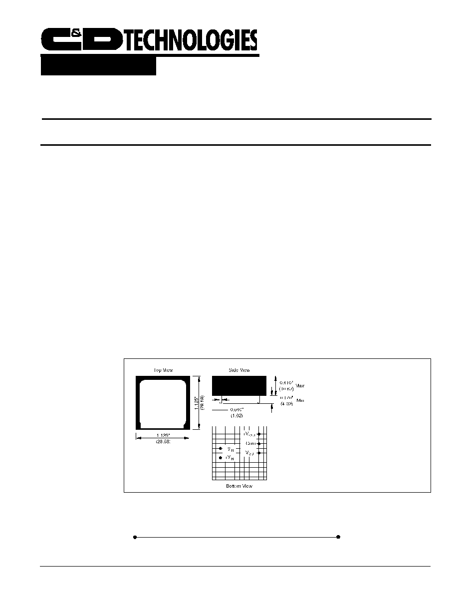
MECHANICAL
NOTES: All dimensions are in inches
(millimeters).
GRID: 0.100 inches (2.54 millimeters)
Marked with: specific model ordered, date
code, job code.
MATERIAL: Units are encapsulated in
a low thermal resistance molding
compound which has excellent
chemical resistance, wide operating
temperature range, and good electrical
properties under high humidity
environments. Lead material is brass
with a solder plated surface to allow
ease of solderability.
PWR72 5/99 REV B
Page 2
ELECTRICAL SPECIFICATIONS
At T
A
= +25∞C, +V
IN
= 15VDC, and I
OUT
= ±100mA unless otherwise noted.
PARAMETER
CONDITIONS
MIN
TYP
MAX
UNITS
INPUT
Rated Voltage
15
V
DC
Voltage Range
5
22
V
DC
Input Current
I
LOAD
= 0
40
mA
I
LOAD
= Rated Load
280
330
mA
Ripple Current
I
LOAD
= 0
15
mApk
I
LOAD
= Rated Load
150
mAp-p
ISOLATION
Rated Voltage
1000
V
DC
Test Voltage
60s, 60Hz
3000
Vpk
Resistance
10
G
Capacitance
10
pF
Leakage Current
V
ISO
= 240VAC, 60Hz
3
µA
OUTPUT
Rated Voltage
±15
V
DC
Voltage Range
I
OUT
= No Load
±15
±20
V
DC
I
OUT
= Rated Load
±14.25
±15.75
V
DC
Rated Power
3
W
Rated Current
100
mA
Total of All Outputs
200
mA
Current Range
Each Output
0
±150
mA
Total of All Outputs
0
300
mA
Line Regulation
10V
DC
Ø V
IN
Ø 18V
DC
1.15
V/V
Load Regulation
0mA Ø I
LOAD
Ø 100mA
15
mV/mA
Ripple Voltage
I
LOAD
= 0
30
mVpk
I
LOAD
= Rated Load
150
mVpk
TEMPERATURE
Specification
≠25
+85
∞C
Operating
≠40
+100
∞C
Storage
≠55
+125
∞C
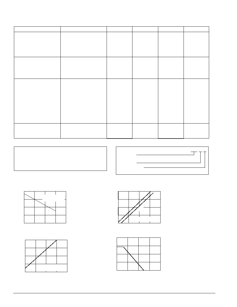
TYPICAL PERFORMANCE CURVES
Typical at T
A
= +25∞C, nominal input voltage, and rated output current unless otherwise noted.
ABSOLUTE MAXIMUM RATINGS
Input Voltage .................................................................................... 22V
DC
Output Short-Circuit Duration ................................................................. Xs
Internal Power Dissipation ..................................................................... 3W
Junction Temperature .................................................................... +175∞C
Package Thermal Resistance ........................................................ 13∞C/W
Lead Temperature (Soldering, 10s) ............................................... +300∞C
Load Current (mA)
Output Voltage (VDC)
19
17
15
13
11
0
100
200
V = 15VDC
Each output loaded
to indicate value.
IN
OUTPUT VOLTAGE
vs LOAD CURRENT
50
150
Input Voltage (VDC)
Output Voltage (VDC)
25
20
15
10
5
5
15
25
Each output loaded
to indicate value.
OUTPUT VOLTAGE
vs INPUT VOLTAGE
10
20
I
=
1
00
m
A
LOAD
I
=
0
LOAD
Ambient Temperature (∞C)
Output Power (W)
10
5
0
0
100
200
POWER DERATING
50
150
Load Current (mA)
Input Current (mA)
400
300
200
100
0
0
100
200
V = 15VDC
Each output loaded
to indicate value.
IN
INPUT CURRENT
vs LOAD CURRENT
50
150
ORDERING INFORMATION
PWR 72 /H
Device Family
PWR indicates DC/DC converter
Model Number
Reliability Screening
No designator indicates standard manufacturing processing
The information provided herein is believed to be reliable; however, C&D TECHNOLOGIES assumes no responsibility for inaccuracies or omissions. C&D TECHNOLOGIES assumes no responsibility
for the use of this information, and all use of such information shall be entirely at the user's own risk. Prices and specifications are subject to change without notice. No patent rights or licenses to any
of the circuits described herein are implied or granted to any third party. C&D TECHNOLOGIES does not authorize or warrant any C&D TECHNOLOGIES product for use in life support devices/systems
or in aircraft control applications.