 | –≠–ª–µ–∫—Ç—Ä–æ–Ω–Ω—ã–π –∫–æ–º–ø–æ–Ω–µ–Ω—Ç: RM4830 | –°–∫–∞—á–∞—Ç—å:  PDF PDF  ZIP ZIP |

RM4830 6/98 REV A
Page 1
30 A
MP
M
ODULAR
S
WITCHED
M
ODE
R
ECTIFIER
RM4830
Product Data Sheet
FEATURES
∑
SWITCHED MODE
∑
> .99 PFC
∑
> 85% EFFICIENCY
∑
HOT-SWAP CAPABLE
∑
AUTOMATIC LOAD SHARING
∑
COMPACT SIZE
∑
SHELF MOUNTED
∑
BELLCORE BASED DESIGN
∑
REMOTE RESTART FUNCTION
!
∑
FRONT PANEL CURRENT METER
∑
BATTERY OR BATTERYLESS OPERATION
∑
INTELLIGENT HIGH VOLTAGE SHUTDOWN
∑
GUARANTEED NO SINGLE PART FAILURE WILL
RESULT IN OUTPUT HIGH VOLTAGE
∑
THD <5%
DESCRIPTION
The RM4830 Modular Switched-Mode Rectifier is one of
C&D Technologies' family of rectifiers that may be used in
modular power plants. This unit will function in parallel
with any rectifier with similar current sharing capacities.
This compact, versatile and efficient unit is ideal for use in
small to medium cellular and PCS sites.
AGENCY APPROVALS
Internet: http://www.cdpowerelectronics.com
Power Electronics Division, United States
3400 E Britannia Drive, Tucson, Arizona 85706
Phone: 800.547.2537 Fax: 520.770.9369
Power Electronics Division, Europe
C&D Technologies (Power Electronics) Ltd.
132 Shannon Industrial Estate, Shannon, Co. Clare, Ireland
Tel: +353.61.474.133 Fax:+353.61.474.141

RM4830 6/98 REV A
Page 2
MEASUREMENTS OF RM4830
Module
Weight
14 lbs.
Height
5 U (8.75")
Depth
15.55"
Width
3.35"
Shelf*
Weight
21 lbs.
Height
5 U (8.75")
Depth
15.55"
Width
23" rack mount
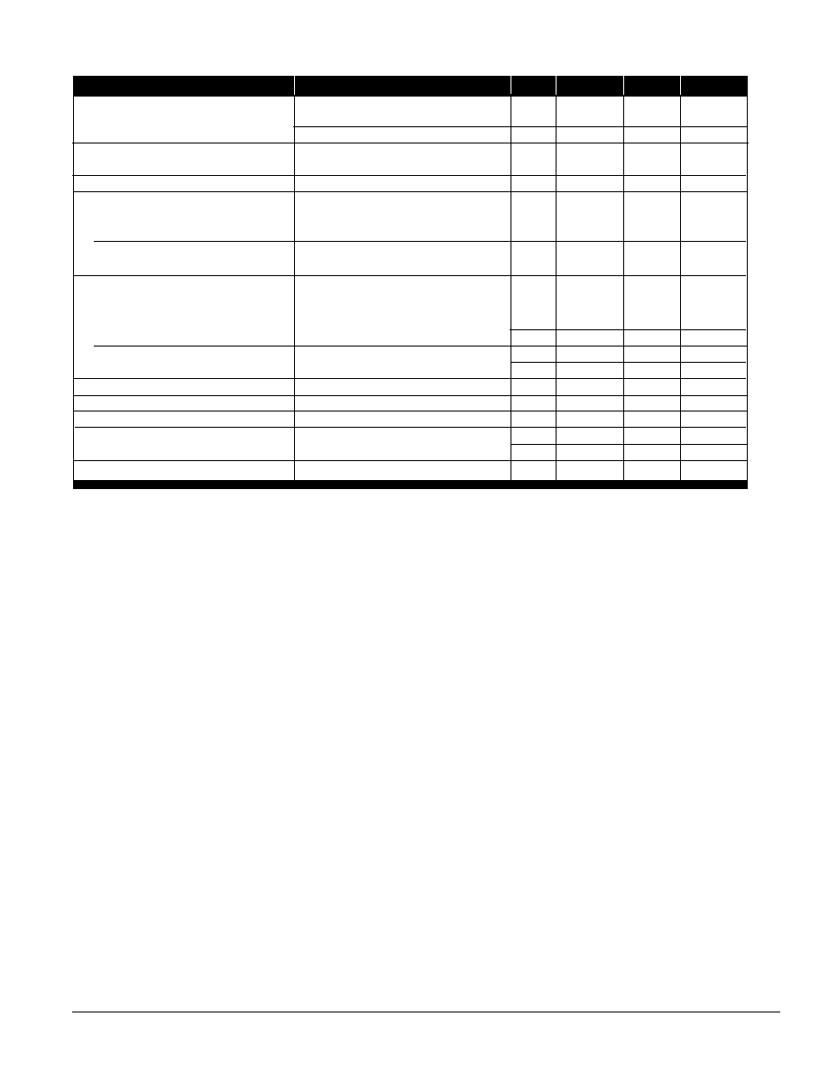
Input Specifications
Parameter
Conditions
Min
Typ
Max
Units
Operating Range
45 - 65 Hz, single phase, no taps required
106
264
V
AC
Current (when supplying 30A
DC
at 48V
DC)
105 V
AC
20
A
AC
208 V
AC
10
A
AC
240 V
AC
8.5
A
AC
Efficiency
> 85
%
Power Factor Correction (PFC)
input range between 105V
AC
-264V
AC
>.99
Hot Swappable Modules
These shelf-mounted modules are easy and safe to install
or remove while system is operational without affecting
the overall system's performance.
Parallel Operation and Automatic Load Sharing
A series of RM4830 rectifiers will automatically share equal
amounts of the load current when operating in parallel
within ±5% of the average current for the load applied.
N+1 Operation
The rectifier can operate in true N + 1 redundacy mode.
Remote Equalize
The rectifier output may be changed from float to equalize
via remote signal.
Current Limit
When rectifier current reaches 30A
DC
- 32A
DC
, the unit
will automatically limit the current down to short circuit con-
ditions with no fold back.
LED Indicators
The front panel includes a 10 segment yellow LED output
current bar graph, a green normal operation LED, and a
red rectifier failed LED.
Safety
UL/CUL Recognized: UL 1950/CSA 950.
File No.: E131694
EMI filtering to FCC and VDE-0875 limits.
GENERAL FEATURES
* These measurements are specifically for the 180A Power Shelf for up to 6 quantity RM 4830.
Please contact factory for other shelf and power plant options.
RM4830 6/98 REV A
Page 3
Output Specifications
Rectifier Failure Alarm (RFA)
Problems occurring because of an unacceptable relation-
ship between the output power and load conditions will
cause a Rectifier Failure Alarm (RFA). This alarm consists
of a red LED. Conditions which may lead to an RFA are:
Low Current - Output current has decreased to below
2% of its rated value.
Unit Shutdown - Any shutdown occurrence due to
overvoltage, external shutdown command, unacceptable
ambient temperature conditions or low AC input voltage.
Fan Malfunction - The fan has stopped operating or is
not providing the airflow needed to cool the unit.
Over Temperature - The ambient temperature has
exceeded 50∞C.
High Voltage Shutdown (HVSD)
The unit's built-in high voltage limit is permanently set at
60.5V
DC
. When internal shutdown occurs, the unit may
be restarted by a local switch or by a remote signal.
Surge Protection
The unit will withstand lightning and input surges of
6000V/3000A.
Under Voltage Protection
When input voltage is below 106 VAC (with tolerance),
the rectifier's operation is automatically inhibited.
Output Circuit Protection Device (Fuse)
The unit has one internal output protection fuse which is
in series with the -48V
DC
output.
PROTECTION, ALARM AND CONTROL SYSTEMS
Parameter
Conditions
Min
Typ
Max
Units
Voltage Adjustment Range
float voltage
40
60
V
DC
equalize voltage
40
60
V
DC
Regulation
0-100% load within
specified input voltage and frequency range
±0.5
%
Load Current
within a 10 - 100% rating
± 10
%
Filtering
Voice band
<32
dBrnC
Wide band noise
20 MHz bandwidth
<250
mV p-p
<40
mVrms
ENVIRONMENTAL
Temperature
Operating
0
+50
∞C
+32
122
∞F
Storage
-50
85
∞C
-58
185
∞F
Temperature Coefficient
after half hour warm-up
0.01
V/∞C
Humidity
non-condensing
0
95
%
Altitude
0
7000
ft.
0
2133
m
Heat Dissipation
@54V
980
Btu/hr
Audible Noise
2 ft. from any vertical surface
<65
dBa

RM4830 6/98 REV A
Page 4
Mechanical
Standard Options are shown, consult factory for other available options.
The information provided herein is believed to be reliable; however, C&D TECHNOLOGIES assumes no responsibility for inaccuracies or omissions. C&D TECHNOLOGIES assumes
no responsibility for the use of this information, and all use of such information shall be entirely at the user's own risk. Prices and specifications are subject to change without notice.
No patent rights or licenses to any of the circuits described herein are implied or granted to any third party. C&D TECHNOLOGIES does not authorize or warrant any C&D TECHNOLOGIES
product for use in life support devices/systems or in aircraft control applications.
4.95
+ .25
4.70
+ .25
2.35
+ .25
4.35
+ .25
14.30
1.25
3.35
8.63
VOLTAGE
FLT EQL
PWR/RESET
30
27
24
21
18
15
12
9
6
3
FAN
SIDE
FRONT
1st TEST BURN-IN
HI-POT
2nd TEST
QA
4830