WPC10R 11/99 REV F
Page 1
FEATURES
G
G
G
G
G SAFETY APPROVALS (
C
UL
US
, CE)
G
G
G
G
G MEETS EN55022 LEVEL A & B FOR CONDUCTED
EMISSIONS WITH A 10 MFD EXTERNAL
CAPACITOR
G
G
G
G
G OPERATING TEMPERATURE RANGE:
-40∞C TO +100∞C
G
G
G
G
G INDUSTRY STANDARD PINOUTS
G
G
G
G
G INDUSTRY STANDARD PACKAGE
G
G
G
G
G LOW PROFILE 0.4 INCH (10MM)
G
G
G
G
G SHORT CIRCUIT PROTECTION
G
G
G
G
G TEMPERATURE SHUTDOWN
G
G
G
G
G REMOTE ON/OFF (OPTIONAL)
G
G
G
G
G LOW RADIATED EMISSIONS
APPLICATIONS
G
G
G
G
G TELECOMMUNICATION APPLICATIONS
G
G
G
G
G BATTERY POWERED SYSTEMS
G
G
G
G
G PORTABLE INSTRUMENTS
G
G
G
G
G PROCESS CONTROL EQUIPMENT
G
G
G
G
G TRANSPORTATION EQUIPMENT
G
G
G
G
G DISTRIBUTED POWER SYSTEMS
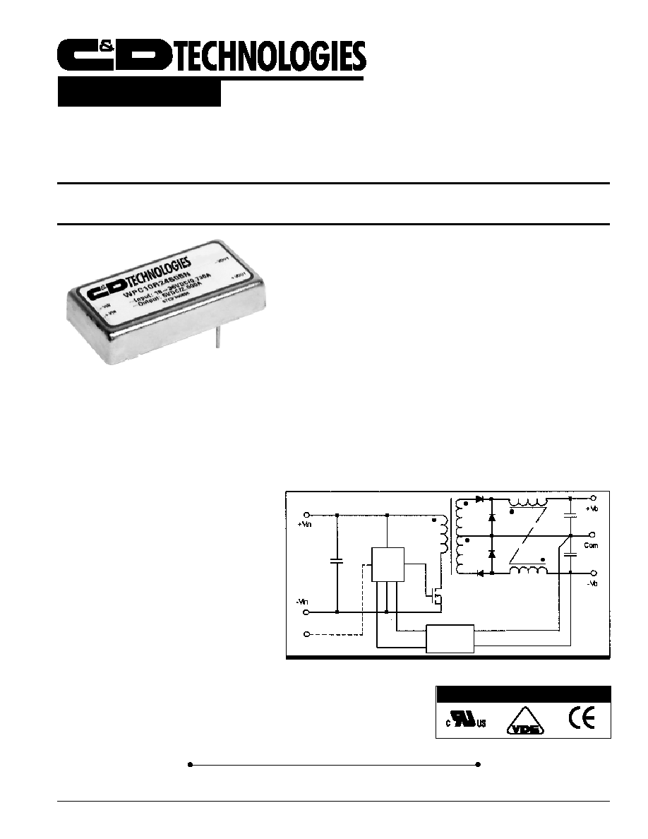
DESCRIPTION
The WPC10R is a family of high performance DC/DC
converters that offer regulated outputs over two input
voltage ranges of 18 - 36 and 28 - 75V and over a wide
operating temperature range of -40∞C to +100∞C without
derating.
The 350kHz switching frequency and forward con-
verter topology provide optimum performance in a space-
saving package. The design uses all surface mounted
components, including magnetics, to provide enhanced
reliability. All models will operate even under no-load
conditions, although a minimum load is specified for load
regulation measurement purposes. A metal package is
utilized for decreased radiated noise and an optional
remote enable feature allows low power standby opera-
tion.
2:1 W
IDE
I
NPUT
R
ANGE
DC/DC C
ONVERTER
WPC10R
Product Data Sheet
AGENCY APPROVALS
SIMPLIFIED CIRCUIT DIAGRAM
OPTICAL
ISOLATION
SHUTDOWN
(OPTIONAL)
CONTROL
Internet: http://www.cdpowerelectronics.com
Power Electronics Division, United States
3400 E Britannia Drive, Tucson, Arizona 85706
Phone: 800.547.2537 Fax: 520.770.9369
Power Electronics Division, Europe
C&D Technologies (Power Electronics) Ltd.
132 Shannon Industrial Estate, Shannon, Co. Clare, Ireland
Tel: +353.61.474.133 Fax:+353.61.474.141

WPC10R 11/99 REV F
Page 2
NOMINAL
RATED OUTPUT CURRENT VOLTAGE REGULATION
INPUT
OUTPUT
VOLTAGE
VOLTAGE MIN LOAD RATED LOAD
LINE LOAD
NOISE
EFFICIENCY
MODEL
(VDC) (VDC)
(mA)
(mA)
(±)
(±)
(mVpp)
(%)
WPC10R24S03
24
3.3
300
3000
0.5%
1%
75
75
WPC10R24S05
24
5
200
2000
0.5%
1%
75
77
WPC10R24S12
24
12
83
833
0.5%
1%
75
78
WPC10R24S15
24
15
67
666
0.5%
1%
75
79
WPC10R24D05
24
±5
±100
±1000
0.5%
2%
75
77
WPC10R24D12
24
±12
±42
±417
0.5%
2%
75
78
WPC10R24D15
24
±15
±33
±333
0.5%
2%
75
79
WPC10R48S03
48
3.3
300
3000
0.5%
1%
75
77
WPC10R48S05
48
5
200
2000
0.5%
1%
75
79
WPC10R48S12
48
12
83
833
0.5%
1%
75
80
WPC10R48S15
48
15
67
666
0.5%
1%
75
81
WPC10R48D05
48
±5
±100
±1000
0.5%
2%
75
79
WPC10R48D12
48
±12
±42
±417
0.5%
2%
75
80
WPC10R48D15
48
±15
±33
±333
0.5%
2%
75
81
ELECTRICAL SPECIFICATIONS
Specifications typical at T
A
= +25∞C, nominal input voltage, rated output current unless otherwise specified.
COMMON SPECIFICATIONS
Specifications typical at T
A
= +25∞C, nominal input voltage, rated output current unless otherwise specified.
PARAMETER
CONDITIONS
MIN
TYP
MAX
UNITS
INPUT
Voltage Range
18
24
36
V
DC
V
IN
=34-75 for 3.3V
out
28
48
75
V
DC
Reflected Ripple Current
20
50
mAp-p
ISOLATION
Test Voltage
60 Hz, 10 Seconds
1500
Vpk
Resistance
10
G
Capacitance
1500
pF
Leakage Current
V
ISO
= 240VAC, 60Hz
100
mArms
OUTPUT
Rated Power
10
Watts
Voltage Setpoint Accuracy
±1
%
Temperature Coefficient
±0.02
%/∞C
Line Regulation
Low Line to High Line
Singles
±0.2
%
Duals
±0.2
%
Load Regulation
Min Load to Rated Load
Singles
±0.2
%
Duals
±0.5
%
Ripple & Noise
BW = 5 Hz to 20 MHz
75
mVp-p
GENERAL
Switching Frequency
350
kHz
MTTF per MIL-HDBK-217, Rev F
Circuit Stress Method,
Ground Benign
T
A
= +25∞C
933
khr
Package Weight
35
g
TEMPERATURE
Specification (ambient)
-25
+71
∞C
Specification (case)
-25
+100
∞C
Operation (case)
-40
+100
∞C
Storage
-55
+125
∞C

WPC10R 11/99 REV F
Page 3
Device Family
Indicates Wide Input Voltage 10 Watt Regulated Unit
Model Number
Selected from Table of Electrical Characteristics
xx = Input Voltage
y = Number of Outputs (Single "S", Dual "D")
zz = Output Voltage
Case Ground Option
"P" = Positive Input Connection
"N" = Negative Input Connection
"F" = Floating Input Connection
Remote ON/OFF (optional)
WPC10R xxyzz N/P/F R
ABSOLUTE MAXIMUM RATINGS
Output Short Circuit Protection
(at T
A
= 25∞C, nominal input voltage) ........................Continuous
Internal Power Dissipation....... ........................................... 2.5W
Lead Temperature (soldering 10seconds, max) ..............+300∞C
Maximum Case Temperature ...........................................+110∞C
ORDERING INFORMATION
THERMAL DERATING CURVE
TOP VIEW
SIDE VIEW
BOTTOM VIEW
NOTES: All dimensions are in inches (millimeters).
GRID: 0.100 inches (2.54 millimeters)
Pin Placement Tolerance: ±0.015
*
Common pins are not present on single output
models
Marked with: specific model ordered, date code, job
code.
MATERIAL: Units are encapsulated in a low thermal resistance molding
compound which has excellent chemical resistance, wide operating
temperature range, and good electrical properties under high humidity
environments. The encapsulant and outer shell of the unit have UL94V-0
ratings. Lead material is brass with a solder plated surface to allow ease of
solderability.
1
2
3
4
5*
6
Pin Connections
1 +Vin
2 -Vin
3 Remote On/Off
4 +Vout
5 Common
6 -Vout
MECHANICAL
REMOTE ON/OFF CONTROL
Logic Compatibility ...................................... CMOS or Open Collector TTL
EC On ................................................................. Open Circuit or > 2VDC
EC Off ........................................................................................ < 1.3VDC
Shutdown Idle Current ..................................................................... <10mA
Control Common ................................................................................. -Vin
Hiweise:
-
Geraet wird mit einer 2A Sicherung abgesichert
-
Eingangspannung muss SELV oder TNV nach
EN60950, IEC60950 entsprechen
-
Ein-und Ausgang des Converters muessen mit dem
Schutzleiter verbunden werden
-
Power supply must be fused with a 2A fuse or current
limited to 2A max
-
Input must be SELV or TNV according to EN60950/
IEC950
-
One input and output pin must be tied to safety earth
ground

WPC10R 11/99 REV F
Page 4
The information provided herein is believed to be reliable; however, C&D TECHNOLOGIES assumes no responsibility for inaccuracies or omissions. C&D TECHNOLOGIES assumes no responsibility
for the use of this information, and all use of such information shall be entirely at the user's own risk. Prices and specifications are subject to change without notice. No patent rights or licenses to any
of the circuits described herein are implied or granted to any third party. C&D TECHNOLOGIES does not authorize or warrant any C&D TECHNOLOGIES product for use in life support devices/systems
or in aircraft control applications.
ENGINEERING NOTES