 | –≠–ª–µ–∫—Ç—Ä–æ–Ω–Ω—ã–π –∫–æ–º–ø–æ–Ω–µ–Ω—Ç: CMI8804 | –°–∫–∞—á–∞—Ç—å:  PDF PDF  ZIP ZIP |
cmi
Capella Microsystems Inc.
3777 Stevens Creek Blvd., Suite 320 Santa Clara, CA 95051-7364 U.S.A Tel: (408) 260-3400 FAX: (408) 248-3416
Copyright © Capella Microsystems 1999 1 CONFIDENTIAL
CMI8804 BTL Driver
For CD/CD-ROM
PRELIMINARY DATA SHEET
Revision 0.1
07/16/99
This preliminary data sheet indicates that this product is still in the design cycle. All specifications
are based on design goals only. Capella Microsystems Inc. assumes no responsibility for the use of this
product.
Capella Microsystems Inc. reserves the right to make changes in specifications or discontinue
this product at any time without notice. Please contact Capella Microsystems Inc. for possible updates
before starting a design.
Capella Microsystems Inc. products are not designed for use in life support applications. Any
parties who use these products in such applications do so at their own risk and agree to fully indemnify
Capella Microsystems Inc. for any damages resulting from such improper usage or sale.
cmi
3777 Stevens Creek Blvd., Suite 320 Santa Clara, CA 95051-7364 U.S.A Tel: (408) 260-3400 FAX: (408) 248-3416
Copyright © Capella Microsystems 1999 2 CONFIDENTIAL
GENERAL DESCRIPTION
The CMI8804 is a silicon monolithic
integrated circuit and is a four channel driver for
optical disc motor drivers. The CMI8804 has a
wide dynamic range of 4.0V(typ.) at
PreVcc=12V, PVcc=5V, and RL=8
. By
separating the into pre+power of sled driver,
power of a loading driver, and power of an
actuator, the CMI8804 has made the power
efficiency better by using low supply voltage.
The CMI8804 has integrated and built in
to itself a level shift circuit, a thermal-shut-down
circuit, and a stand-by mode. The actuator
drive is a current feedback type and the current
phase lag influenced load inductance is little.
On the sled motor driver, input pins consist of
(+) and (-), which thus provides various input
types, such as the differential input. The
loading driver is a single input linear BTL driver.
FEATURES
Focus Actuator which controls the height of
the pickup to maintain the proper focus.
Tracking Actuator which moves the pickup
along the closet track.
Sled Motor Control which moves the pickup
to a track other than the immediate track.
Tray Motor Control which opens and closes
the tray when inserting or removing the disc.
APPLICATIONS
CD-ROM DRIVES
CD DRIVES
Stand-by
1
2
3
4
5
6
7
8
9
11
12
13
14
18
17
16
15
21
20
26
25
24
23
28
27
Thermal
Shut Down
+
-
+
-
+
-
+
-
+
-
+
-
10
19
22
Sled
Driver
Actuator
Driver
Loading
Driver
Actuator
Driver
+
-
7.5K
10K
20K
7.5K
10K
20K
7.5K
7.5K
x2
x2
Det. Amp
Det. Amp
10K
25K
10K
15K
PreGND
PVcc2
PGND
PVcc2
PGND
PVcc1
Vcc
PVcc1
Vcc
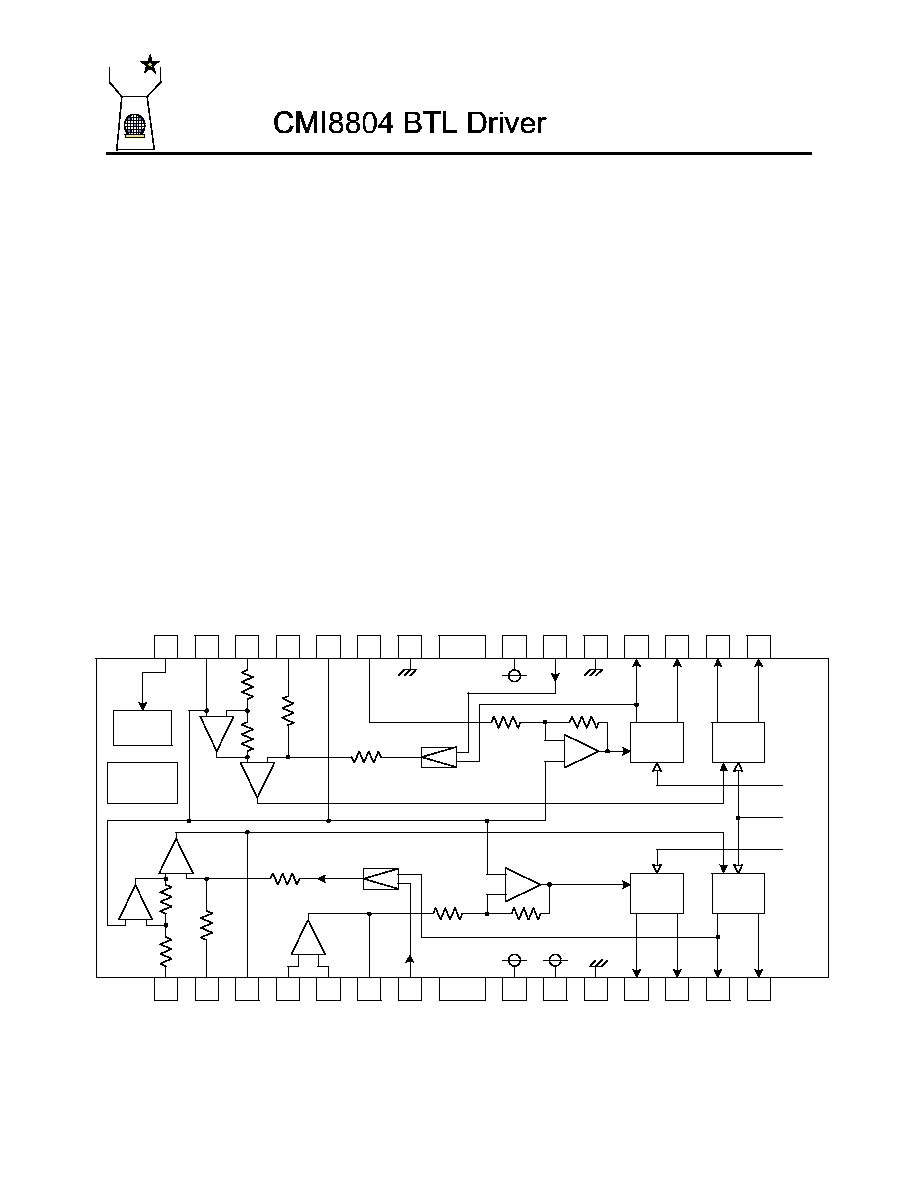
Figure 1: CMI8804 Block Diagram

cmi
3777 Stevens Creek Blvd., Suite 320 Santa Clara, CA 95051-7364 U.S.A Tel: (408) 260-3400 FAX: (408) 248-3416
Copyright © Capella Microsystems 1999 3 CONFIDENTIAL
Pin Description
Pin #
Pin
Name
Description
Pin #
Pin
Name
Description
1
VINFC
Input for focus driver
28
STBY
Input for stand-by control
2
CFCerr1
Connection with capacitor
27
BIAS
Input for reference voltage
3
CFCerr2
for error amplifier
26
VINTK
Input for tracking driver
4
VINSL+
Non inverting input for OP-
amp
25
CTKerr1
for error amplifier
5
VINSL-
Inverting input for OP- amp
24
CTKerr2 Connection with capacitor
6
VOSL
Output of OP- amp
23
VINLD
Input for loading driver
7
VNFFC
Feedback for focus driver
22
PreGND GND for pre-drive block
8
Vcc
Vcc for pre-drive block and
power block of sled
21
PVcc2
Vcc for power block of actuator
9
PVcc1
Vcc for power block of loading
20
VNFTK
Feedback for tracking driver
10
PGND
GND for power block
19
PGND
GND for power block
11
VOSL-
Inverted output of sled
18
VOLD-
Inverted output of loading
12
VOSL+
Non inverted output of sled
17
VOLD+
Non inverted output of loading
13
VOFC-
Inverted output of focus
16
VOTK-
Inverted output of tracking
14
VOFC+
Non inverted output of focus
15
VOTK+
Non inverted output of tracking
Note: Symbol of + and ≠ (output of drivers) means polarity to input pin.
(For example, if the voltage of pin 1 is high, pin 14 is high.)
Absolute Maximum Ratings
Characteristic
Symbol
Rating
Unit
Supply Voltage
Vcc, PVcc1/2
13.5
V
Power Dissipation
Pd
1.7*
W
Operating Temperature
Topr
-35 ~ 85
∞
C
Storage Temperature
Tstg
-55 ~ 155
∞
C
* On less than 3% (percentage occupied by copper foil),
70x70mm
3
, t=1.6mm, glass epoxy mounting. Reduce power
by 13.6mW for each degree above 25
∞
∞
C.
Recommended Operating Conditions
Characteristic
Symbol
Rating
Unit
Vcc
4.3 ~ 13.2
PVcc1
4.3 ~ Vcc
Supply Voltage
PVcc2
4.3 ~ Vcc
V

cmi
3777 Stevens Creek Blvd., Suite 320 Santa Clara, CA 95051-7364 U.S.A Tel: (408) 260-3400 FAX: (408) 248-3416
Copyright © Capella Microsystems 1999 4 CONFIDENTIAL
Electrical Characteristics
(Ta=25
∞
∞
C, Vcc=12V, PVcc1=PVcc2=5V, BIAS=2.5V, RL=8
, Rd=0.5
, C=100pF)
Description
Signal
Condition
min
typ
max
Unit
Quiescent Current
I
-
1.8
2.7
mA
Stand-by Quiescent Current
I
-
-
0.5
mA
Voltage for Stand-by ON
V
STON
-
-
0.5
V
Voltage for Stand-by OFF
V
STOFF
2.0
-
-
V
Actuator Driver
Output Offset Current
I
CO
-6
-
6
mA
Maximum Output Voltage
V
OU
3.6
4.0
-
V
Trans Conductance
gm
V
IN
= BIAS
±
0.2V
1.3
1.5
1.7
A/V
Sled Motor Driver/Pre OP-Amp
Common Mode Input Range
V
ICN
-0.3
-
11.0
V
Input Bias Current
I
SOP
-
30
300
nA
Low Level Output Voltage
V
OLOP
-
0.1
0.3
V
Output Source Current
I
SO
0.3
0.5
-
mA
Output Sink Current
I
ST
1
-
-
mA
Sled Motor Driver
Output Offset Voltage
V
OOPSL
-100
0
100
mV
Maximum Output Voltage
V
OMSL
7.5
9.0
-
V
Closed Loop Voltage Gain
G
VSL
V
IN
=
±
0.2V
18.0 20.0 22.0
dB
Loading Motor Driver
Output Offset Voltage
V
OOPLO
-50
0
50
mV
Maximum Output Voltage
V
OULD
3.6
4.0
-
V
Closed Loop Voltage Gain
G
VLD
V
IN
= BIAS
±
0.2V
13.5 15.5 17.5
dB
Gain Error by Polarity
G
VLD
V
IN
= BIAS
±
0.2V
0
1
2
dB
Note: For reference to Electrical Characteristics, see figure 4 (page 6), CMI8804 Test Circuit.
This product is not designed for protection against radioactive rays.
25
50
75
100
125
150
175
3
2
1
0
Ambient Temperature - Ta (∞C)
Pd (w)
Note: On less than 3% (percentage occupied by copper
foil), 70x70mm
3
, t=1.6mm, glass epoxy mounting.
Figure 2: CMI8804 Power Dissipation/Electrical Characteristic Curves
cmi
3777 Stevens Creek Blvd., Suite 320 Santa Clara, CA 95051-7364 U.S.A Tel: (408) 260-3400 FAX: (408) 248-3416
Copyright © Capella Microsystems 1999 5 CONFIDENTIAL
Stand-by
1
3
4
7
8
9
11
12
13
14
18
17
16
15
21
20
24
28
Thermal
Shut Down
+
-
+
-
+
-
+
-
+
-
+
-
Sled
Driver
Actuator
Driver
Loading
Driver
Actuator
Driver
+
-
7.5K
10K
20K
7.5K
10K
20K
7.5K
7.5K
x2
x2
Det. Amp
Det. Amp
10K
25K
10K
15K
PreGND
PVcc2
PGND
PVcc2
PGND
PVcc1
Vcc
PVcc1
Vcc
2
25
23
22
19
10
6
5
27
26
M
M
5V or 12V
5V or 12V
12V
Sled
Motor
Focus
Coil
Loading
Motor
Tracking
Coil
Rd
Rd
Sled
Focus
Tracking
Vccenter
Stand-by
Loading
DSP
µ
-COM
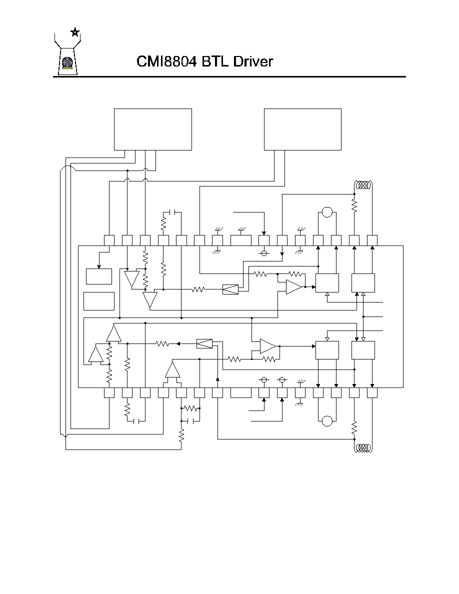
Figure 3: CMI8804 Application Circuit