Specifications are subject to change without notice (19.07.06)
1
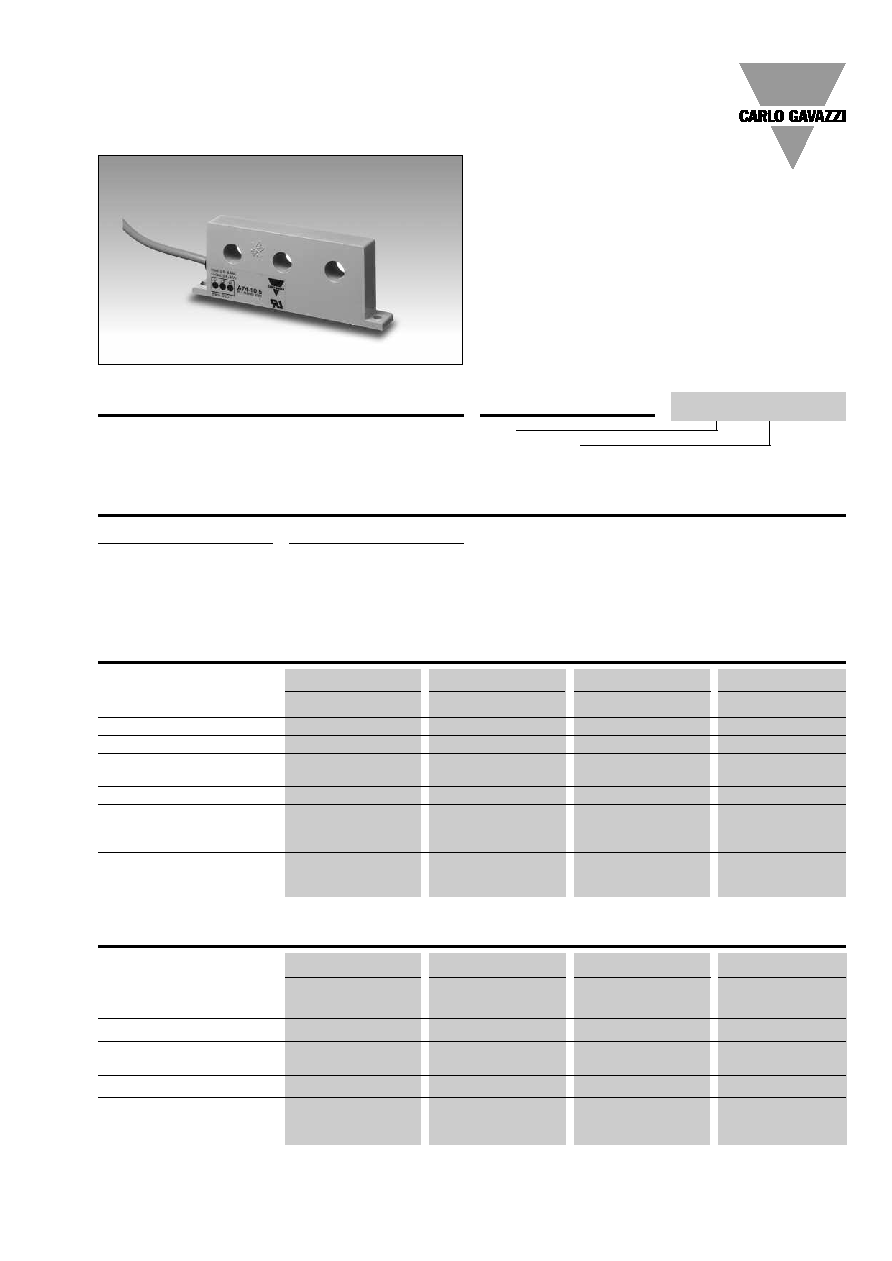
Current and Voltage Controls
∑ 3-phase current metering transformers
for use with current control relays
∑ Measuring ranges:
A 74-10 5:
0.5 -
5 AAC
A 74-10 20:
2
- 20
AAC
A 74-11 100: 10
- 100 AAC
A 74-11 500: 50
- 500 AAC
Product Description
3-phase current transformer
measures on all three phases.
Output voltage proportional
Ordering Key
Type
Input current
to measured amplitude of the
rms-value of the normal
phase current.
Type Selection
Input current
Type no.
5 AAC
A 74-10
5
20 AAC
A 74-10 20
100 AAC
A 74-11 100
500 AAC
A 74-11 500
Input Specifications
A 74-10 5
A 74-10 20
A 74-11 100
A 74-11 500
Output voltage
(T
A
= 20∞C = 68∞F), R
L
= 9.5 k
)
0.4 - 4 V
p
0.4 - 4 V
p
0.4 - 4 V
p
0.4 - 4 V
p
Output impedance
< 700
< 200
< 40
< 10
Tolerance of output voltage
@ rated input current
± 5%
± 5%
± 5%
± 5%
Temperature variation
± 0.1% per ∞C
± 0.1% per ∞C
± 0.1% per ∞C
± 0.1% per ∞C
Rated insulation voltage (cable)
250 VAC
rms
250 VAC
rms
250 VAC
rms
250 VAC
rms
Output Specifications
Current Transformer, 3-Phase
Types A 74-10, A 74-11
A 74-10 5
A 74-10 20
A 74-11 100
A 74-11 500
Current range
0.5 - 5 AAC
2 - 20 AAC
10 - 100 AAC
50 - 500 AAC
Max. current (continuously)
20 AAC
50 AAC
250 AAC
750 AAC
Max. overload current (t = 30 s)
40 AAC
85 AAC
325 AAC
1000 AAC
Rated insulation voltage
Input-output
1000 VAC
rms
1000 VAC
rms
1000 VAC
rms
1000 VAC
rms
Overvoltage category
IV (IEC 60664)
IV (IEC 60664)
IV (IEC 60664)
IV (IEC 60664)
Dielectric strength
Dielectric voltage
6 kVAC
rms
6 kVAC
rms
6 kVAC
rms
6 kVAC
rms
Rated impulse withstand volt.
12 kV (1.2/50 µs)
12 kV (1.2/50 µs)
12 kV (1.2/50 µs)
12 kV (1.2/50 µs)
Power consumption
< 0.1 W@5 A
< 0.25 W@20 A
< 1.5 W@100 A
< 21 W@1500 A
A 74-10 5
2
Specifications are subject to change without notice (19.07.06)
A 74-10, A 74-11
General Specifications
Pollution degree
3 (IEC 60664)
Ambient temperature
- 20 to + 60∞C (- 4 to + 140∞F)
Housing
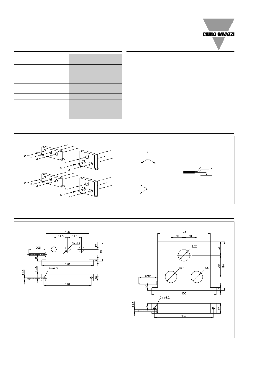
Dimensions
A74-10
120 x 45 x 16 mm
A74-11
150 x 114 x 23
Material
ABS
Weight
A 74-10
200 g
A 74-11
750 g
Connection cable
2 m PVC, 4 x 0.4 mm
2
Approval
UL
CE Marking
Yes
The current metering trans-
former is connected to the
current control relays H 475
as follows:
Red core to term. 5
- U
1
.
White core to term. 6
- U
2
.
Yellow core to term. 7
- U
3
.
Black core to term. 8.
(starpoint - neutral).
The metered conductor is
drawn through the central
hole of the current metering
transformer. Drawing the con-
Mode of Operation
ductor through the hole sever-
al times makes it possible to
meter currents below the no-
minal range.
If the conductor is drawn
through the central hole e.g. 5
times, the metering trans-
former will register 50 A when
the current in the conductor is
10 A.
In amplitude and phase the
output voltage is proportional
to the phase current metered.
Wiring Diagrams
Output voltage
A 74-10 ..
A 74-11 ..
Input current
Red
White
Yellow
Black
U
1
Red
Black
U
3
Yellow
U
2
White
U
1
Red
U
2
White
U
3
Yellow
Black
Dimensions
Correct connection
Incorrect connection