 | –≠–ª–µ–∫—Ç—Ä–æ–Ω–Ω—ã–π –∫–æ–º–ø–æ–Ω–µ–Ω—Ç: AA1004 | –°–∫–∞—á–∞—Ç—å:  PDF PDF  ZIP ZIP |
Specifications are subject to change without notice SPT-90DS0303
1
∑ Class 0.5 (current/voltage)
∑ 16-bit µP-based modular smart power transducer
∑ Measurements of: W, Wavg, VA, VAr, PF, Wh, VAh, VArh,
Amax (among the phases), V
L
-
L
avg, VL1-N, VL2-N,
VL3-N, Hz L1.
∑ TRMS measurement of distorted waves (voltage/current)
∑ All configuration functions selectable by an optional
removable key-pad or programming software SptSoft
∑ Password protection of programming parameters
∑ Optional independent alarm setpoint
∑ Optional second analogue output (20 mADC/±20mADC
±10 mADC/±5 mADC/10 VDC/±5VDC/±1VDC)
∑ Optional serial RS 422/485 or RS232 output
∑ MODBUS, JBUS protocol.
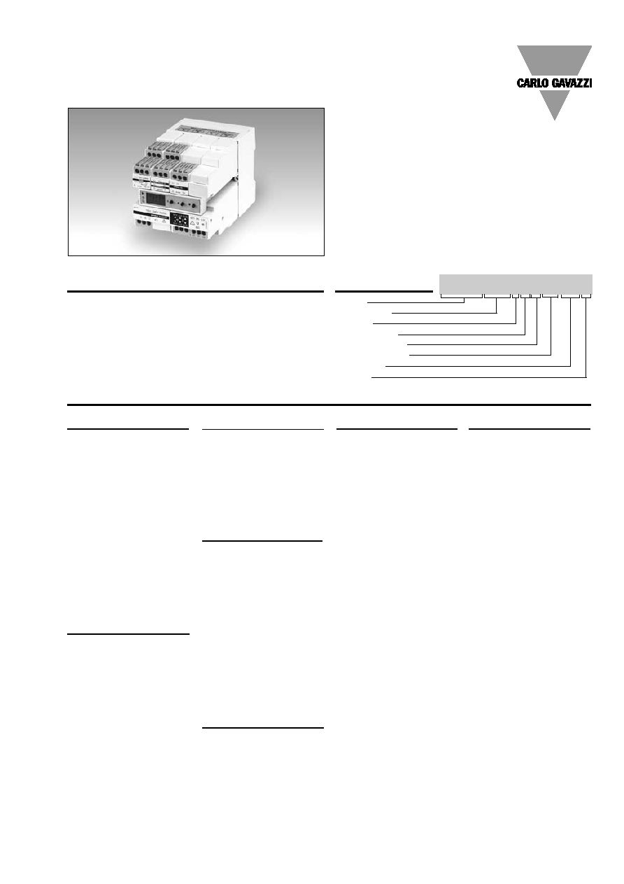
Product Description
Model
Range code
System
Power supply
Auxiliary output
1st output/input
2nd output
Options
Ordering Key SPT-90AV51HXA1XXX
16-bit µP-based modular
smart power transducer with
an optional removable con-
figuration key-pad or pro-
gramming software. The
housing is for DIN-rail mount-
ing and ensures a degree of
protection (front) of IP 20.
Energy Management
Modular Smart Power Transducer
Type SPT-90
Type Selection
System
1:
One phase, three-
phase system
(3 or 4 wires, balan-
ced load)
3:
Three phase system
(3 or 4 wires, unba-
lanced load)
Range code
AV1:
100/
3/100 VAC-1 AAC
(max. 130/
3 (L-N)/
130 V (L-L) - 1.2 A)
1)
AV3:
100/
3/100 VAC-5 AAC
(max. 130/
3 (L-N)/
130 V (L-L) - 6 A)
1)
AV4:
250/433 VAC - 1 AAC
(max. 300 V (L-N)/
520 V (L-L) - 1.2 A)
1)
AV5:
250/433 VAC - 5 AAC
(max. 300 V (L-N)/
520 V (L-L) - 6 A)
(standard)
AV7:
400/690 VAC - 5 AAC
(max. 480 V (L-N)/
830 V (L-L) - 6 A)
1)
Power supply
L:
18 to 60 VAC/DC
H:
90 to 260VAC/DC
Auxiliary output
X:
None (standard)
D:
Single Alarm setpoint,
relay
1)
(AO1058)
P:
Single Pulse, open
collector, DC type
1)
(AO1059)
B
Dual pulse output,the
second one is the
copy of the first one,
like "P"
1)
(AO1036)
T
Dual alarm output,
the second one is the
copy of the first one,
like "D"
1)
(AO1035)
1st output/input
D1(*): 3 digital inputs
(managed only by
means of the serial
communication)
1)
A1:
Single analogue output,
20mADC (standard)
A2:
Single analogue output,
±5mADC
1)
A3:
Single analogue output,
±10mADC
1)
A4:
Single analogue output,
±20mADC
1)
B1:
Dual analogue output,
20mADC (standard)
B2:
Dual analogue output,
±5mADC
1)
B3:
Dual analogue output,
±10mADC
1)
B4:
Dual analogue output,
±20mADC
1)
V1:
Single analogue output,
10VDC (standard)
V2:
Single analogue output,
±1VDC
1)
V3:
Single analogue output,
±5VDC
1)
V4:
Single analogue output,
±10VDC
1)
W1:
Dual analogue output,
10VDC (standard)
W2:
Dual analogue output,
±1VDC
1)
W3:
Dual analogue output,
±5VDC
1)
W4:
Dual analogue output,
±10VDC
1)
2nd output
XX:
None (standard)
S1:
Serial port, RS 485
multidrop bidirec-
tional
1)
A1:
Analogue output,
20 mADC (standard)
A2:
Analogue output,
±5 mA
1)
A3:
Analogue output,
±10 mA
1)
A4:
Analogue output,
±20 mA
V1:
Analogue output,
10 VDC
1)
V2:
Analogue output,
±1 VDC
1)
V3:
Analogue output,
±5VDC
1)
V4:
Analogue output,
±10VDC
1)
1)
On request
Options
X:
None
K:
Programming key-pad
S:
RS232 port
2)
2)
The programming software has the part number: Sptsoft
(*) The 3 digital inputs can't work together with one or more analogue outputs in the same instrument.

2
Specifications are subject to change without notice SPT-90DS0303
SPT-90
Output Specifications
Number of inputs
Current
2 (system code: 1)
6 (system code: 3)
Voltage
2 (system code: 1)
4 (system code: 3)
Digital
4, for 3 free of voltage con-
tacts (inputs managed only
by the serial communica-
tion)
Reading voltage/current:
17.5 to 25VDC/<8mA
Accuracy (basic unit)
Voltage/current
±0.5% f.s. includes also:
frequency, power supply
and output load influences
Frequency
±0.5% f.s. (45 to 500 Hz)
Active power
(@ 25∞C ± 5∞C, R.H.
60%)
±0.5% f.s. (PF 0.7 L/C,
0.6 to 1 In, 0.9 to 1.1 Un)
±1% f.s. (PF 0.3 L/C,
0.2 to 1.2 In, 0.7 to 1.2 Un)
Reactive power
(@ 25∞C ± 5∞C, R.H.
60%)
±0.5% f.s. (PF 0.7 L/C,
0.6 to 1 In, 0.9 to 1.1 Un)
±1% f.s. (PF 0.3 L/C,
0.2 to 1.2 In, 0.7 to 1.2 Un)
Apparent power
(@ 25∞C ± 5∞C, R.H.
60%)
±0.5% f.s.,
(0.6 to 1 In, 0.9 to 1.1 Un)
±1% f.s.,
(0.2 to 1.2 In, 0.7 to 1.2 Un)
Additional errors
Humidity
0.3% f.s., 60% to 90% R.H.
Input frequency
0.4% f.s., 62 to 400 Hz
Magnetic field
0.5% f.s. @ 400 A/m
Ripple
1% according to IEC 60688-1
and EN60688-1
Sampling rate
1900 Hz
Display (programming unit)
7-segment, LED, h 9 mm
Max. and min. indication
Max. 999, min. -999
Measurements
W, Wavg, VA, VAr, PF, Wh,
VAh, VArh, Amax (among the
phases), VL-L avg, VL1-N,
VL2-N, VL3-N, Hz L1.
TRMS measurement of a dis-
torted wave voltage/current
Coupling type : Direct
Crest factor:
3
Ranges (impedances)
AV1 (Un/In):
100 V /
3/100 V (>250k) -
1 AAC (
0.3 VA)
AV3 (Un/In):
100 V /
3/100 V (>250k) -
5 AAC (
0.3 VA)
AV4 (Un/In):
250 V/433 V (>450k
) -
1 AAC (
0.3 VA)
AV5 (Un/In):
250 V/433 V (>450k
) -
5 AAC (
0.3 VA)
AV7 (Un/In):
400 V/690 V (>1M
) -
5 AAC (
0.3 VA)
Frequency range
48 to 62 Hz
Over-load protection
Continuous: voltage/current
1.2 Un/In
For 1 s
Voltage:
2 Un
Current:
20 In
Programming keypad
Removable type
(on request)
3 keys: "S" for enter pro-
gramming phase and
password confirmation,
"UP" and "DOWN" for
value programming/function
selection
Programming software
SptSoft Programming soft
ware (on request) for
windows 95/98 combined
with an RS232 serial
communication module.
Input Specifications
±20mA output
550
±10 mA output
1100
±5 mA output
2200
10 V output
10 k
±10 V output
10 k
± 5 V output
10 k
± 1 V output
10 k
Insulation
By means of optocouplers,
4000 V
rms
output to
measuring input
4000 V
rms
output to
supply input
Serial port (on request)
Type
RS422/RS485, multidrop
bidirectional (static and
dynamic variables)
Connections
4-wire, termination
directly on the module
Addresses
255, selectable by key-pad
Protocol
MODBUS/JBUS
Analogue outputs
Number of outputs
1 (standard) + 1 (on request)
Accuracy
±0.2% f.s. (@ 25∞C±5∞C,
R.H.
60%)
Range
0 to 20 mADC,
±5mADC, ±10mADC,
±20mADC, 10VDC, ±1VDC,
±5VDC, ±10VDC.
Scaling factor
Programmable within the
whole range of retransmis-
sion; it allows the retrans-
mission management of all
values from: 0 to 20 mADC,
±5mADC, ±10mADC,
±20mADC, 0 to10VDC,
±1VDC, ±5VDC, ±10VDC.
Response time
250 ms typical
(filter excluded)
Temperature drift
300 ppm/∞C
Load:
20 mA output
600

Specifications are subject to change without notice SPT-90DS0303
3
SPT-90
Password
Numeric code of max. 3 di-
gits; 2 protection levels of
the programming data
1st level
Password "0", no protection
2nd level
Password from 1 to 499, all
data are protected
Measurement selection
System's active power (W),
system's apparent power
(VA), system's reactive
power (VAr), average active
power (Wavg), integration
time programmable from 1
to 30 minutes, system's
power factor (cos
), maxi-
mum current (A max), avera-
ge phase-phase voltage,
phase-neutral voltage-
phase 1, phase-neutral vol-
tage-phase 2, phase-neutral
voltage-phase 3, frequency-
phase 1.
System's (+) active energy,
system's apparent energy,
Measurement selection (cont.) system's reactive energy,
system's (+/-) active energy
Transformer ratio
For CT up to 5000 A,
For VT up to 100 kV (1MV)
Scaling factor
Operating mode
Electrical scale: compression/
expansion of the input scale
to be connected to 1 or 2 ana-
logue outputs and to the alarm
output.
Electrical range
Programmable within the
whole measuring range
Filter
Filter operating range
0 to 99.9% of the
input electrical scale
Filtering coefficient
1 to 255
Filter action
Both analogue and serial
outputs (fundamental vari-
ables: V, A, W and their
derived ones)
Software Functions
Serial port (cont.)
Data (bidirectional)
Dynamic (reading only)
System variables:
P, P
AVG
, S, Q, PF, V
L-L
, f,
energy and status of digital
inputs, setpoint output and
status of the energy over-
flow bit,
Single phase variables:
P
L1
, S
L1
, Q
L1,
PF
L1
, V
L1-N
, A
L1
,
P
L2
, S
L2,
Q
L2
, PF
L2
, V
L2-N
, A
L2
,
P
L3
, S
L3,
Q
L3
, PF
L3
, V
L3-N
, A
L3
Static (writing only)
All programming data, reset
of energy, reset of energy
overflow bit, activation of
static output.
Stored energy (EEPROM)
250,000.000 kWh
Data format
1-start bit, 8-data bit, no
parity/even parity, 1 stop bit
Baud-rate
1200, 2400, 4800 and 9600
selectable bauds
Insulation
By means of optocouplers,
4000 V
rms
output to
measuring inputs
4000 V
rms
output to
supply input
Temperature drift
200 ppm/∫C
RS 232 port (on request)
bidirectional (static and
dynamic variables)
3 wires, max. distance 15m
Data format
1-start bit, 8-data bit,
no parity, 1 stop bit
Baud-rate
9600 bauds
Protocol
MODBUS (JBUS)
Other data
as for RS422/485
Pulse output (on request)
Number of outputs
1, independent
Type
From 1 to 999 programmable
pulses for kWh, KVAh,
KVArh, MWh, MVAh,
MVArh,
open collector (NPN transistor)
V
ON
1.2 VDC/ max. 100mA
V
OFF
30 VDC max.
according to DIN43864
Pulse duration
20 ms (ON),
20 ms (OFF)
Insulation
By means of optocouplers,
4000 V
rms
output to
measuring input,
4000 V
rms
output to
supply input.
Alarms (on request)
Number of setpoints
1, independent
Alarm type
Up alarm, down alarm
Setpoint adjustment
0 to 100% of the electrical
scale
Hysteresis
0 to 100% of the electrical
scale
On-time delay
0 to 255 s
Relay status
Normally de-energized
Output type
Relay, SPDT
AC 1 - 8A @ 250VAC
DC 12 - 5A @ 24VDC
AC 15 - 2.5 @ 250VAC
DC 13 - 2.5 @ 24VDC
Response time
typ. 250 ms, filter excluded,
setpoint on-time delay: "0"
Insulation
4000 V
rms
output to
measuring input,
4000 V
rms
output to
supply input
Output Specifications (cont.)
4
Specifications are subject to change without notice SPT-90DS0303
SPT-90
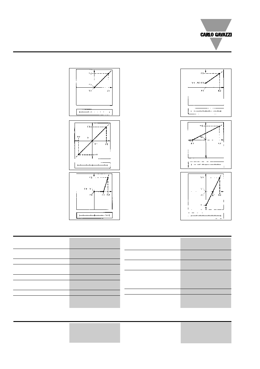
Function Description
Figure A
The sign of measured quant-
ity and output quantity re-
mains the same. The output
quantity is proportional to the
measured quantity.
Input and output scaling capability
Working of the analogue outputs (y) versus input variables (x)
Figure B
The sign of measured quant-
ity and output quantity
changes simultaneously. The
output quantity is proportion-
al to the measured quantity.
Figure C
The sign of measured quant-
ity and output quantity re-
mains the same. On the
range X0...X1, the output
quantity is zero. The range
X1...X2 is delineated on the
entire output range Y0 =
Y1...Y2 and thus presented in
strongly expanded form.
Figure F
The sign of the measured
quantity remains the same,
that of the output quantity
changes as the measured
quantity leaves range X0...X1
and passes to range X1...X2
and vice versa.
Figure E
The sign of the measured
quantity changes but that of
the output quantity remains
the same. The output quant-
ity steadily increases from
value X1 to value X2 of the
measured quantity.
Figure D
The sign of measured quant-
ity and output quantity re-
mains the same. With the
measured quantity being
zero, the output quantity
already has the value
Y1 = 0.2 Y2.
Live zero output.
0 50 A
100
A
0 10 mA
20
mA
-100 kW
0 100 kW
-1 kW
0 1 kW
80 V
100 V
120 V
0 5 mA 10
mA
0
50 A 100 A
4 12 mA 20 mA
-100 kW
0
100 kW
0
10 mA
20 mA
0
50 A 100 A
-1 V
0
1 V
Operating temperature
0 to +50∞C (32 to 122∞F)
(R.H. < 90% non-condensing)
Storage temperature
-10 to +60∞C (14 to 140∞F)
(R.H. < 90% non-condensing)
Insulation reference voltage
300 V
rms
to ground
Insulation
4000 V
rms
between all inputs/
outputs to ground
Dielectric strength
4000 V
rms
for 1 minute
Noise rejection
CMRR
100 dB, 48 to 62 Hz
EMC
EN 50081-2, EN 50082-2
Other standards
Safety requirements:
IEC 61010-1, EN 61010-1
Product requirements:
IEC 60688-1, EN 60688-1
Pulse output:
DIN 43864
Approvals
CE
UL, CSA
Connector
Screw-type,
max. 2.5 mm
2
wires x 2
Housing
Dimensions
90 x 90 x 140 mm
Material
ABS,
self-extinguishing: UL 94 V-0
Degree of protection
IP20
Weight
Approx. 550 g
(packing included)
General Specifications
AC voltage
90 to 260 VAC/DC (standard),
50/60 Hz
18 to 60VAC/DC, 50/60Hz
(on request),
Power consumption
30 VA / 20W (90 to 260V)
20VA / 20W (18 to 60V)
Supply Specifications
Specifications are subject to change without notice SPT-90DS0303
5
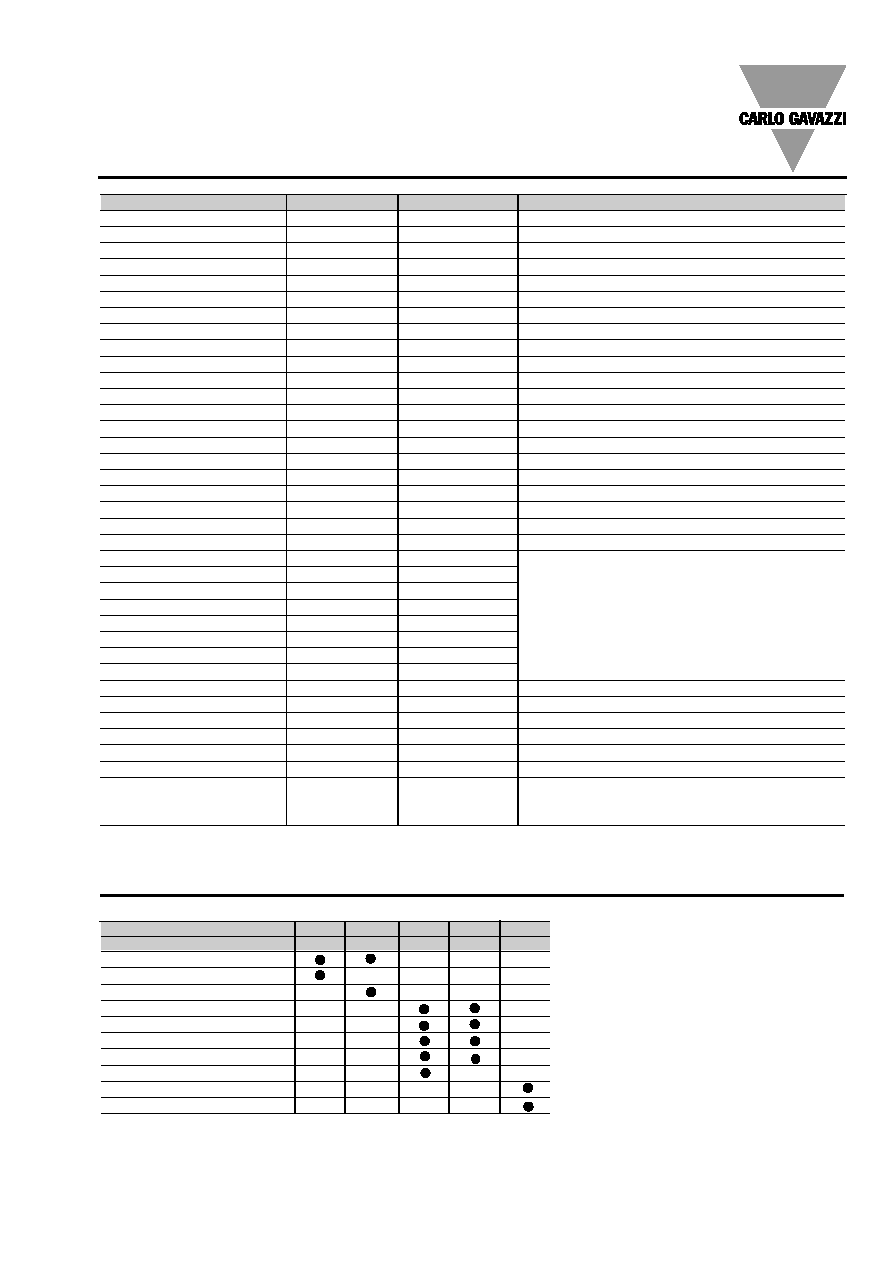
SPT-90
Slot
A
B
C
D
E
Basic unit
Out 1
Out 2
Out 3 Out 4
PU
Single analogue output (2)
Dual analogue output (2)
RS485 port (1)
Single relay output (alarm)
Single open coll. output (pulse)
Dual relay output (alarm)
Dual open coll. output (pulse)
3 digital inputs (2)
(*)
RS232 port (1)
Programming unit
Type
N. of channels
Ordering code
Note
SPT-90 base + AV1.1 input
AA1000
SPT-90 base + AV3.1 input
AA1001
SPT-90 base + AV4.1 input
AA1002
SPT-90 base + AV5.1 input
AA1003
SPT-90 base + AV7.1 input
AA1004
SPT-90 base + AV1.3 input
AA1006
SPT-90 base + AV3.3 input
AA1007
SPT-90 base + AV4.3 input
AA1008
SPT-90 base + AV5.3 input
AA1009
SPT-90 base + AV7.3 input
AA1010
18-60VAC/DC power supply
AP1021
90-260VAC/DC power supply
AP1020
Programming unit
AR1017
The same unit can be used in several SPT's
20mADC analogue output
1
AO1050
10VDC analogue output
1
AO1051
±5mADC analogue output
1
AO1052
±10mADC analogue output
1
AO1053
±20mADC analogue output
1
AO1054
±1VDC analogue output
1
AO1055
±5VDC analogue output
1
AO1056
±10VDC analogue output
1
AO1057
20mADC analogue output
2
AO1026
SPT can be equipped also with 2 dual analogue
10VDC analogue output
2
AO1027
outputs, in this case the third or fourth output can
±5mADC analogue output
2
AO1028
be used as a redundant output of the second one
±10mADC analogue output
2
AO1029
±20mADC analogue output
2
AO1030
±1VDC analogue output
2
AO1031
±5VDC analogue output
2
AO1032
±10VDC analogue output
2
AO1033
RS485 port
1
AR1034
Relay output
1
AO1058
Relay output
2
AO1035
The second output can be used as redundant output
Open collector output
1
AO1059
Open collector output
2
AO1036
The second output can be used as redundant output
Digital inputs
3
AQ1038
RS232 port + RTC
1
AR1039
The RS232 module works as alternative of the
RS485 module. The RTC (real time clock) function
is not available in the SPT
The available modules
The possible combinations
Notes:
PU is the programming unit
(1) The RS232 module works as alternative
of the RS485 module.
(2) (*) Digital inputs and analogue outputs can't
work together in the same instrument.