Specifications are subject to change without notice EM4-DINDS1003
1
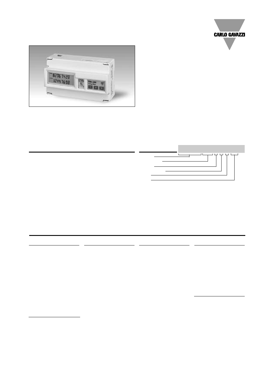
Product description
Three-phase energy meter
with built-in configuration
key-pad; particularly indicat-
ed for the metering and the
management of the energy
in addition to the metering
and the management of the
signals coming from the
water and gas meters.
Housing for DIN-rail or wall-
mounting, IP40 (front) pro-
tection degree.
Completely sealable housing.
In case of direct connection
up to 90A, the measuring
input terminals are suitable
for cables with a cross-sec-
tion area from 6 to 35 mm
2
.
The special design of the
instrument's housing allows
to add at any time the inter-
face modules, even when
the instrument is already
installed. The following mod-
ules are available:
- for all versions: pulse output;
- only for the versions with
auxiliary power supply:
digital inputs, RS485 serial
port.
Energy Management
Energy Meter with plug-in Output Modules
Type EM4-DIN
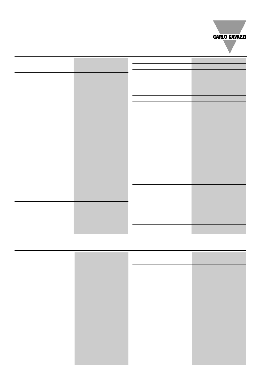
Type selection
Power supply
For all versions
A:
24VAC
-15+10%, 50-60Hz
B:
48VAC
-15+10%, 50-60Hz
C:
115VAC
-15+10%, 50-60Hz
D:
230VAC
-15+10%, 50-60Hz
4:
18 to 60VDC
5:
77 to 143VDC
AV2, AV8 and AV9 only
X:
Self Power Supply
400V
L-L
(-20+15%, 50-60Hz)
208V
L-L
(-20+15%, 50-60Hz)
220V
L-L
(-10+15%, 50-60Hz)
Range Code
Auxiliary Power Supply:
AV0:
208V
L-L
/20(90)AAC [3]
AV1:
400V
L-L
/20(90)AAC [1]
AV3:
660V
L-L
/20(90)AAC [2]
AV4:
208V
L-L
/5(10)AAC [3]
AV5:
400V
L-L
/5(10)AAC [1]
AV6:
100V
L-L
/5(10)AAC [3]
AV7:
660V
L-L
/5(10)AAC [2]
Self Power Supply:
AV2:
220V
L-L
/20(90)AAC [4]
AV8:
208V
L-L
/20(90)AAC [1]
AV9:
400V
L-L
/20(90)AAC [1]
Slot A (retransmission)
X:
None
O:
AO2900 module
Dual open collector out-
put. Three operating
modes:
�
two pulse outputs
(kWh and kvarh);
�
one alarm output
(kW dmd) and one
pulse output
(kWh or kvarh)
�
one output
remotely controlled
by a serial port
and one pulse
output (kWh or kvarh)
D:
AQ2940 module
Two digital inputs for
the management of
water and gas meters
Slot A (retransmission) cont.
R:
AO2910 module.
One relay output + one
open collector output.
Operation modes like
module AO2900
Slot B (retransmission)
Only with A-B-C-D-4
power supply
XX:
None
S0:
AR2950 module
RS422/485
serial port
Model
Range code
System
Power supply
Slot A
Slot B
How to order EM4-DIN AV5 3 X X XX
System
3 :
Three-phase,
unbalanced load with
or without neutral
[1] Un: -20+15% [2] Un: -30+15% [3] Un: -20+20% [4] Un: -10 +15%
�
Class 1 (active energy)
�
Class 2 (reactive energy)
�
Three-phase multi-function energy meter
�
Back-lighted LCD display
�
3
1
/
2
DGT instantaneous variables read-out
�
8 DGT + 7
1
/
2
DGT energy read-out
�
Measurements of system and phase variables: W, Wdmd
�
Measurements of total energies: kWh, kvarh
�
Measurements of partial energies: kWh, kvarh
�
Energy measurements according to EN61036 and EN61268
�
Energy measurements by time periods (t1-t2-t3-t4)
selectable by input contacts
�
Measurements of m
3
H
2
O and m
3
GAS by means of input contacts
�
TRMS measurements of distorted wave forms
(voltages/currents)
�
Two basic models: direct connection 20(90)AAC,
CT 5(10)AAC and VT connection
�
Self power supply (available for some models only) or
auxiliary power supply: 24V, 48V, 115V, 230V, 50-60Hz;
18 to 60VDC, 77 to 143VDC
�
Degree of protection (front): IP 40
�
Front dimensions: 9 DIN modules
�
RS 422/485 Serial port by means of optional module
�
Dual pulse output by means of optional module
�
Alarm output (kW dmd) by means of optional module
�
Digital inputs for the management of the time periods
and of the H
2
O and GAS meters
Important note:
�
The models from AV0 to AV7 can be equipped with any
type of available modules (slot A and B).
�
The models AV8 and AV9 can be equipped only with the
"O" and "R" type modules.
�
The AV8 and AV9 models can measure all the parameters
even if the three phase system being connected is missing
one phase.
�
The AV2 model is suitable only for three-phase unbalanced
system without neutral.
2
Specifications are subject to change without notice EM4-DINDS1003
EM4-DIN
2000 V
RMS
output to
supply input
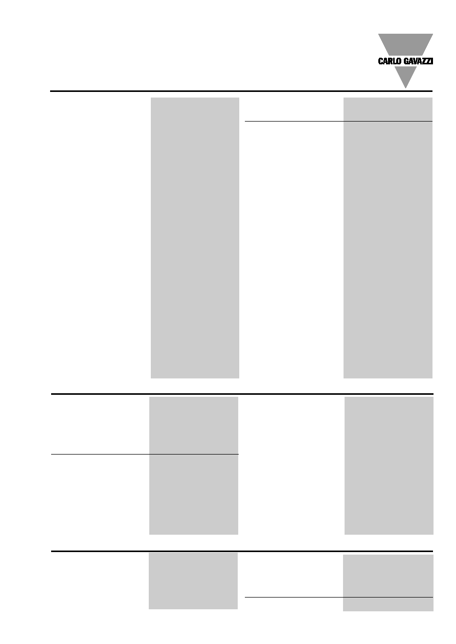
Digital outputs (on request)
AO2900 module
To be used as energy
retransmission, water and
gas, remote static outputs
and alarm. Three working
modes are selectable:
�
two pulse outputs
(kWh and kvarh);
�
one alarm output (kW
dmd) and one pulse
output (kWh or kvarh);
�
one output remotely con-
trolled by means of the
serial port and one pulse
output (kWh or kvarh)
Pulse outputs
Number of outputs
2
Number of pulses
From 0.01 to 100 pulses
programmable according to
the selected CT and VT ratios
Output type
Open collector (NPN transistor )
V
ON
1.2 VDC / max. 100 mA
RS422/RS485 (on request)
AR2950 module
Type
Multidrop
bidirectional (static
and dynamic variables)
Connections
2 or 4 wires, max. distance
1200m, termination directly
on the module
Addresses
255, selectable by key-pad
Protocol
MODBUS/JBUS
Data (bidirectional)
Dynamic (reading only)
Phase and system variables:
see table "Display pages"
Static (writing only )
All the programming data,
reset of energy, activation of
static output.
Stored energy (EEPROM)
max. 99.999.999 kWh/kvarh
Data format
1 start bit, 8 data bit,
no parity, 1 stop bit
Baud-rate
9600 bit/s
Insulation
By means of optocouplers,
2000 V
RMS
output
to measuring inputs
Number of inputs
Current
3
Voltage
4
Accuracy (display, RS485)
Ib: 5A, Imax: 10A
Ib: 20A, Imax:90A
Un: see "Range code" on
previous page
Current
from 0.003Ib to 0.2Ib:
�(0.5%RDG +3DGT)
from 0.2Ib to Imax:
�(0.5%RDG +1DGT)
Voltage
in the range Un:
�(0,5% RDG + 1DGT)
Frequency
�0.1% RDG (50 to 60 Hz)
Active power
(@ 25�C � 5�C, R.H.
90%)
�(1% RDG +1DGT). PF 1,
0.1Ib to Imax, in the Un range;
PF 0.5L, PF 0.8C, 0.2Ib to
Imax, in the Un range
Energies
(@ 25�C � 5�C, R.H.
90%)
Class 1 acc. to EN61036
Class 2 acc. to EN61268
Ib: 5A, Imax: 10A
0.1Ib: 500mA,
Start up current: 20mA
Un: see table "range code"
Ib: 20A, Imax: 90A
0.1Ib: 2A,
Start up current: 80mA
Un: see table "range code"
Additional errors
Acc. to EN61036, EN61268
Wave form
<1% (3
rd
harmonic: 10%)
Voltage asymmetry
< 0.5% (referred to Un)
Magnetic induction
0 (up to 0.5 mT)
HF Electromagnetic fields
< 1%
Operation of accessories
0
Temperature drift
200ppm/�C
Sampling rate
1000 samplings/s @ 50Hz
Display
Type
Back-lighted LCD
Instantan. variables read-out
3
1
/
2
DGT
Energies
Total: 8 DGT + 7
1
/
2
DGT;
Partial: 8 DGT + 7
1
/
2
DGT;
Max. and Min. indication
Max. 1999 (99999999), Min. 0
Measurements
Power, energy.
TRMS measurements of
distorted wave forms.
Coupling type
Direct
Crest factor
Ib 5A
3 (15A max. peak)
Ib 20A
6 (127A max. peak)
Current overload
5(10) A, for 10ms
300A max, @ 50Hz
5(10) A, for 500ms
200A max, @ 50Hz
5(10) A, permanent
10A, @ 50Hz
20(90) A, for 10ms
2700A max, @ 50Hz
20(90) A, permanent
90A, @ 50Hz
Voltage overload
Permanent
1.2 Un
For 1s
2 Un
Input impedance
400
V
L-L
(
AV1-AV5-AV9)
> 720K
208V
L-L
(
AV0-AV4-AV8-AV2)
> 720K
660V
L-L
(
AV3-AV7)
> 1.97M
100V
L-L
(
AV6)
> 400K
5(10) A (AV4-AV5-AV6-AV7)
< 0.3VA
20(90) A (AV0-AV1-AV3-AV8-AV9) < 4VA
20(90) A (AV2)
< 4VA
Frequency
50 to 60 Hz
Interface module specifications
Input specifications
Specifications are subject to change without notice EM4-DINDS1003
3
EM4-DIN
V
OFF
30 VDC max.
Pulse duration
220 ms (ON),
220 ms (OFF)
According to DIN43864
Alarm output
Number of outputs
1
Alarm type
Up alarm, down alarm.
Setpoint adjustment
0 to 100% of the electrical
scale
Hysteresis
0 to 100% of the electrical
scale
On-time delay
0 to 255 seconds
Response time
700 ms
Output type
Open collector (transistor NPN)
V
ON
1.2 VDC / max. 100 mA
V
OFF
30 VDC max.
Insulation
By means of optocouplers,
2000 V
RMS
outputs to
measuring inputs,
2000 V
RMS
output to
supply input.
Insulation between the two
outputs: functional
AO2910 module
Relay + open collector
output. Working mode like
AO2900.
Pulse output
One static output+one relay
output, other characteristics
like AO2900.
Alarm output
Only relay output, other
characteristics like AO2900.
Output type
Static type like module
AO2900;
Relay type: SPDT,
AC1, AC15: 1AAC @250VAC
Insulation
2000 V
RMS
outputs to
measuring inputs,
2000 V
RMS
output to
supply input.
Insulation between the two
outputs: 2000 V
RMS
Digital inputs (on request)
AQ2940 module
Four working modes are
selectable:
�
total and partial energy
meters (kWh and kvarh)
without the use of digital
inputs
�
total and partial energy
meters (kWh and kvarh)
managed by time periods
(t
1
-t
2
-t
3
-t
4
);
�
total energy meters
(kWh, kvarh) and total
"day-time/night" GAS
meter;
�
total energy meters
(kWh, kvarh), GAS
and WATER meters;
Number of inputs
2
Input frequency
20Hz max.
Duty cycle
50%
Prescaler adjustment
from 0,1 to 100,0 m
3
/ pulse
Contact measur. voltage
12V < +Aux < 24VDC
Logic status:
OFF < 2V, ON > 10V
Contact measur. current
15mA max
Input impedance
1k
Contact resistance
1k
, close contact
100k
, open contact
Insulation
By means of optocouplers,
2000 V
RMS
digital inputs to
measuring inputs,
2000 V
RMS
digital inputs to
supply input.
Interface module specifications (cont.)
to 5A)
Display
Variables
Up to 4 variables per page
Page 1: kWh-kvarh
Page 2a: k Wh (t
1
-t
2
-t
3
-t
4
)
k varh (t
1
-t
2
-t
3
-t
4
)
Page 2b: GAS m
3
day-time tariff,
GAS m
3
night tariff
Page 2c: H
2
O m
3
, GAS m
3
Page 3: W
L1
Page 4: W
L2
Page 5: W
L3
Page 6: W
dmd
Errors
Phase sequence, serial
communication status, wrong
connection of current
measuring inputs.
Password
Numeric code of max.
3 digits
2 protection levels of the
programming data
1
st
level
Password "0", no protection
2
nd
level
Password from 1 to 1000,
all data are protected
Transformer ratio
CT
1 to 5000
VT
1.0 to 199.9 and 200 to 1999
Note: The CT ratio * VT ratio
mustnever exceed the
value 5000. The current
measuring inputs can
manage CT's with a
secondary of 1A and 5A
(accuracy always refers
Software functions
Self supplied version
400V
L-L
(-20% +15%, 50-60Hz)
208V
L-L
(-20% +15% , 50-60Hz)
220V
L-L
(-10+15%, 50-60Hz)
Auxiliary power supply
230VAC -15 +10%, 50-60Hz
115VAC -15 +10%, 50-60Hz
48VAC; -15 +10%, 50-60Hz
24VAC; -15 +10%, 50-60Hz
18 to 60VDC; 77 to 143VDC
Energy consumption
7VA
Supply specifications
4
Specifications are subject to change without notice EM4-DINDS1003
EM4-DIN
Variables that can be displayed
No
1
st
variable
2
nd
variable
Notes
1
kWh
kvarh
2a
kWh (t
1
or t
1
-t
2
-t
3
-t
4
)
kvarh (t
1
or t
1
-t
2
-t
3
-t
4
)
Depending on the type of selection you have chosen.
2b
Day-time GAS m
3
Night GAS m
3
For the energy it is possible to choose the following operating mode:
2c
H
2
O m
3
GAS m
3
t
1
partial meters or t
1
-t
2
-t
3
-t
4
multitariff selection
3
W
L1
4
W
L2
5
W
L3
6
W
dmd
dmd = demand (integration time selectable from 1 to 30 min.)
7
Display of the serial communication status, phase sequence, wrong connection of current measuring inputs
Display pages
Pulse voltage (1.2/50�s)
8kV (EN61000-4-5)
Standards
Safety
IEC60664-1
Metrology
Energy measurements:
EN61036, EN61268.
Pulse output
DIN43864
Approvals
CE
Connections 5(10) A
Screw-type,
Cable cross-section area
4 mm
2
Connections 20(90) A
Screw-type,
Min./Max. cable cross-section area
6 mm
2
/ 35 mm
2
Min./Max. screws tightening torque 2 Nm / 6 Nm (90A inputs)
Housing
Dimensions
162.5 x 90 x 63 mm
Material
ABS, NORYL, PC
self-extinguishing: UL 94 V-0
Mounting
DIN-rail and wall
Degree of protection
Front: IP40
Connections: IP20
Weight
800 g approx. (packing included)
Operating
0 to +55�C
temperature
(R.H. < 90% non-condensing
40�C)
Storage
-20 to +60�C
temperature
(R.H. < 90% non-condensing
40�C)
Installation category
Cat. III (IEC60664)
Insulation
2000 V
RMS
between all inputs /
outputs to earth
Dielectric strength
4000 V
RMS
for 1 minute
Noise rejection
CMRR
100 dB, 48 to 62 Hz
EMC
Burst
4kV/level 4 (EN61000-4-4)
Immunity to irradiated
electromagnetic fields
10V/m 26-1000MHz
(EN61000-4-3)
Electrostatic discharges
15kV (EN61000-4-2)
Radio frequency emissions
according to CISPR 14
and CISPR 22
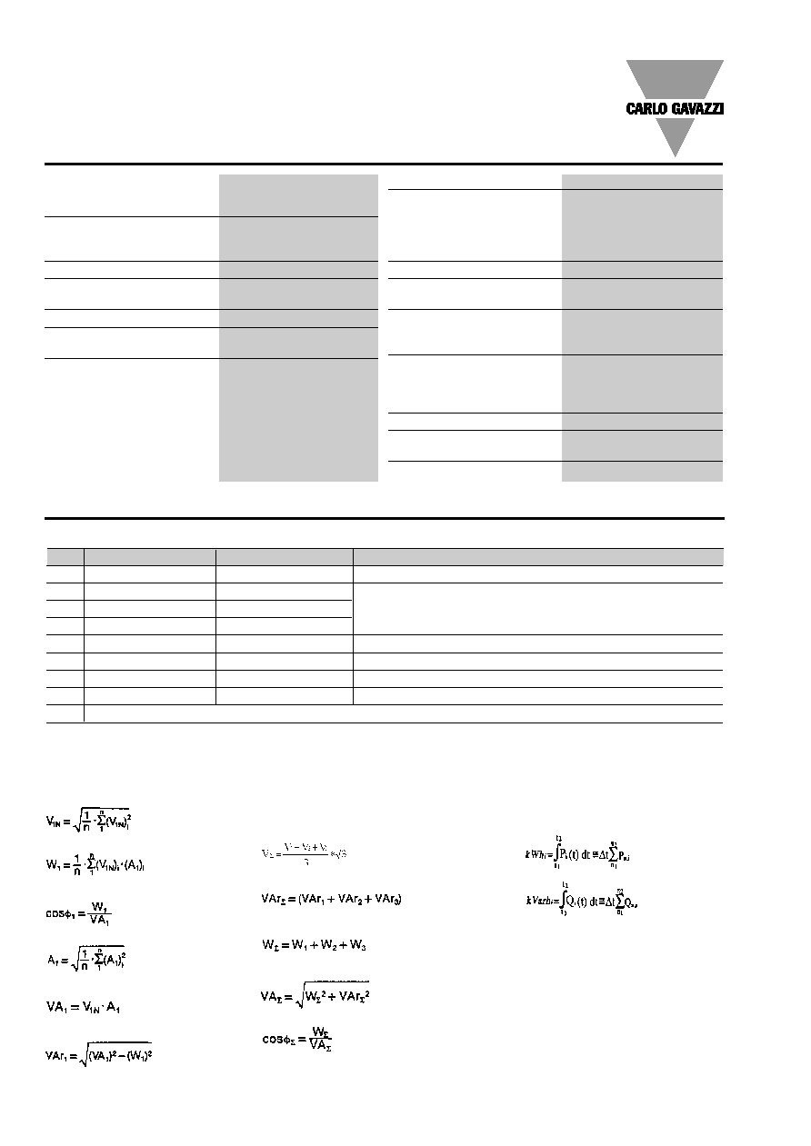
General Specifications
System variables
Equivalent system voltage
System reactive power
System active power
System apparent power
System power factor
(TPF)
Used calculation formulas
Phase variables
Instantaneous effective voltage
Instantaneous active power
Instantaneous power factor
(TPF)
Instantaneous effective current
Instantaneous apparent power
Instantaneous reactive power
Consumption recording
Note:
i = phase (L1, L2 or L3)
P = active power
Q = reactive power
t
1
, t
2
= starting and ending time
points of consumption recording
n = time unit
t= time interval of consumption
recording
n
1
, n
2
= starting and ending discrete
time points of consumption recording
Note: RS422/RS485 "dynamic data". The variables transmitted are the ones listed in
the table above and those mentioned in the "Display pages" of WM22-DIN data
sheet except for: THD
A
, THD
V
, A max, W
dmd
max, and VA
dmd
max.
Specifications are subject to change without notice EM4-DINDS1003
5
EM4-DIN
Type
Inputs
Power supply
Ordering code
EM4-DIN AV9.3.X.
400V
L-L
, 20(90)A
Self power supply
AG2200
EM4-DIN AV8.3.X.
208V
L-L
, 20(90)A
Self power supply
AG2201
EM4-DIN AV2.3.x
220V
L-L
, 20(90)A
Self power supply
AG2244
EM4-DIN AV1.3.D.
400V
L-L
, 20(90)A
230VAC, 50-60Hz
AG2202
EM4-DIN AV0.3.D.
208V
L-L
, 20(90)A 230VAC,
50-60Hz
AG2203
EM4-DIN AV3.3.D.
660V
L-L
, 20(90)A
230VAC, 50-60Hz
AG2204
EM4-DIN AV1.3.C.
400V
L-L
, 20(90)A
115VAC, 50-60Hz
AG2205
EM4-DIN AV0.3.C.
208V
L-L
, 20(90)A
115VAC, 50-60Hz
AG2206
EM4-DIN AV3.3.C.
660V
L-L
, 20(90)A
115VAC, 50-60Hz
AG2207
EM4-DIN AV1.3.B.
400V
L-L
, 20(90)A
48VAC, 50-60Hz
AG2208
EM4-DIN AV0.3.B.
208V
L-L
, 20(90)A
48VAC, 50-60Hz
AG2209
EM4-DIN AV3.3.B.
660V
L-L
, 20(90)A
48VAC, 50-60Hz
AG2210
EM4-DIN AV1.3.A.
400V
L-L
, 20(90)A
24VAC, 50-60Hz
AG2211
EM4-DIN AV0.3.A.
208V
L-L
, 20(90)A
24VAC, 50-60Hz
AG2212
EM4-DIN AV3.3.A.
660V
L-L
, 20(90)A
24VAC, 50-60Hz
AG2213
EM4-DIN AV5.3.D.
400V
L-L
, 5(10)A
230VAC, 50-60Hz
AG2214
EM4-DIN AV4.3.D.
208V
L-L
, 5(10)A
230VAC, 50-60Hz
AG2215
EM4-DIN AV7.3.D.
660V
L-L
, 5(10)A
230VAC, 50-60Hz
AG2216
EM4-DIN AV5.3.C.
400V
L-L
, 5(10)A
115VAC, 50-60Hz
AG2217
EM4-DIN AV4.3.C.
208V
L-L
, 5(10)A
115VAC, 50-60Hz
AG2218
EM4-DIN AV7.3.C.
660V
L-L
, 5(10)A
115VAC, 50-60Hz
AG2219
EM4-DIN AV5.3.B.
400V
L-L
, 5(10)A
48VAC, 50-60Hz
AG2220
EM4-DIN AV4.3.B.
208V
L-L
, 5(10)A
48VAC, 50-60Hz
AG2221
EM4-DIN AV7.3.B.
660V
L-L
, 5(10)A
48VAC, 50-60Hz
AG2222
EM4-DIN AV5.3.A.
400V
L-L
, 5(10)A
24VAC, 50-60Hz
AG2223
EM4-DIN AV4.3.A.
208V
L-L
, 5(10)A
24VAC, 50-60Hz
AG2224
EM4-DIN AV7.3.A.
660V
L-L
, 5(10)A
24VAC, 50-60Hz
AG2225
EM4-DIN AV6.3.D.
100V
L-L
, 5(10)A
230VAC, 50-60Hz
AG2226
EM4-DIN AV6.3.C.
100V
L-L
, 5(10)A
115VAC, 50-60Hz
AG2227
EM4-DIN AV6.3.B.
100V
L-L
, 5(10)A
48VAC, 50-60Hz
AG2228
EM4-DIN AV6.3.A.
100V
L-L
, 5(10)A
24VAC, 50-60Hz
AG2229
EM4-DIN AV1.3.4 / [5]
400V
L-L
, 20(90)A
18-60VDC [77-143VDC]
AG2230 [AG2237]
EM4-DIN AV0.3.4 / [5]
208V
L-L
, 20(90)A
18-60VDC [77-143VDC]
AG2231 [AG2238]
EM4-DIN AV3.3.4 / [5]
660V
L-L
, 20(90)A
18-60VDC [77-143VDC]
AG2232 [AG2239]
EM4-DIN AV5.3.4 / [5]
400V
L-L
, 5(10)A
18-60VDC [77-143VDC]
AG2233 [AG2240]
EM4-DIN AV4.3.4 / [5]
208V
L-L
, 5(10)A
18-60VDC [77-143VDC]
AG2234 [AG2241]
EM4-DIN AV7.3.4 / [5]
660V
L-L
, 5(10)A
18-60VDC [77-143VDC]
AG2235 [AG2242]
EM4-DIN AV6.3.4 / [5]
100V
L-L
, 5(10)A
18-60VDC [77-143VDC]
AG2236 [AG2243]
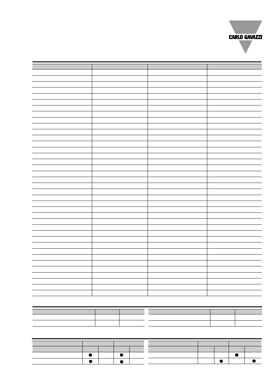
Available models
Possible module combinations
Available modules
Power supply
Self p.s.
Auxiliary p.s.
Basic unit
Slot A Slot B Slot A Slot B
Digital inputs
RS485 Serial Output
(*) AV2 only
Type
Channels
Code
Open collector output
2
AO2900
Relay + open coll. output
2
AO2910
Power supply
Self p.s.
Auxiliary p.s.
Basic unit
Slot A Slot B Slot A Slot B
Open collector output
Relay + open coll. output
Type
Channels
Code
Digital inputs
2
AQ2940
RS485 Serial Output
1
AR2950
(*)
6
Specifications are subject to change without notice EM4-DINDS1003
EM4-DIN
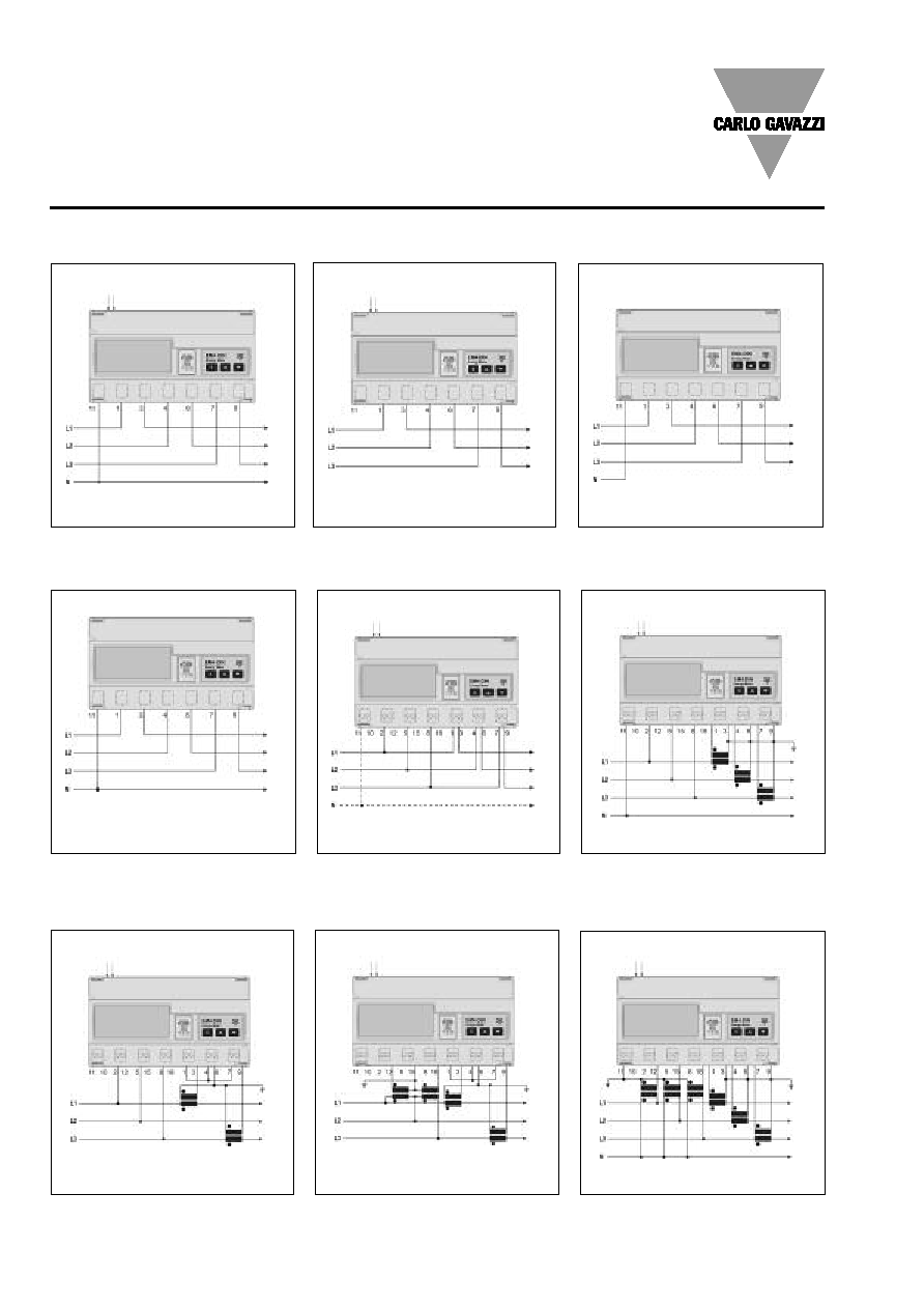
Wiring diagrams
20(90)A model: three-phase unbalanced load
Direct connection (3-phase system w/out N )
Direct connection (3-phase system)
Direct connection (3-phase system + N)
Self-power supply
Fig. 3
5(10)A model:
three-phase unbalanced load
Direct connection (3-phase system + N)
Direct connection (3-phase system
with or without neutral)
CT connection (3-phase system with neutral)
Self-power supply
Fig. 4
5(10)A model: three-phase unbalanced load
VT and CT connection (3-phase system)
20(90)A model:
three-phase unbalanced load
Auxiliary power supply
Fig. 2
Auxiliary power supply
Fig. 1
Auxiliary power supply
Fig. 5
Auxiliary power supply
Fig. 6
Auxiliary power supply
Fig. 9
AC power supply
AC power supply
AC power supply
AC power supply
AC power supply
L
O
A
D
L
O
A
D
L
O
A
D
L
O
A
D
L
O
A
D
L
O
A
D
L
O
A
D
CT ARON connection (3-phase system)
VT and CT ARON connection (3-phase system)
Auxiliary power supply
Fig. 8
Auxiliary power supply
Fig. 7
AC power supply
AC power supply
L
O
A
D
L
O
A
D
Specifications are subject to change without notice EM4-DINDS1003
7
EM4-DIN
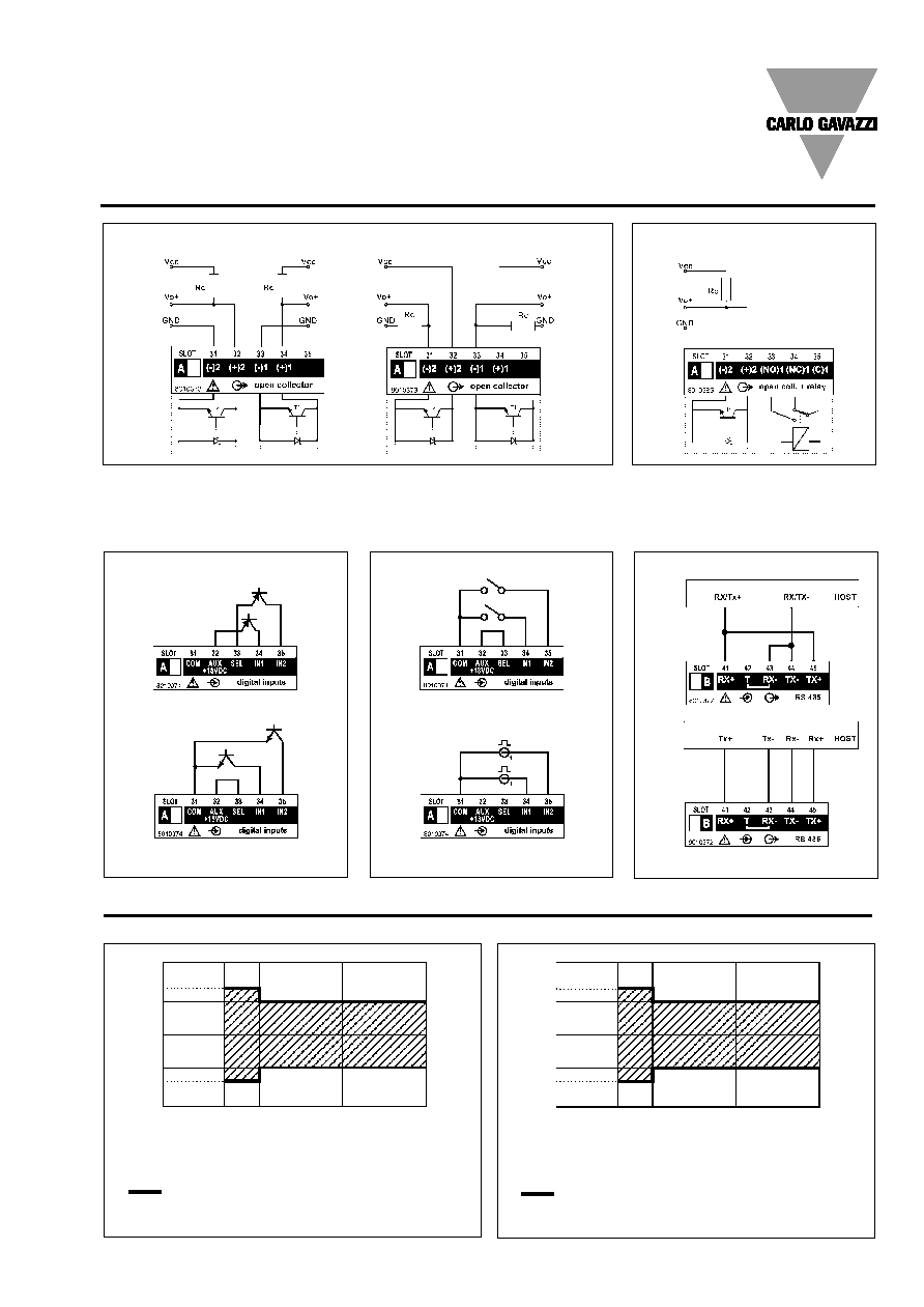
Wiring diagrams (optional modules)
Only open collector outputs: the grounds of the outputs are separated, and therefore it's possible to carry out, for the same
module, two different connections. The load resistance (Rc) must be designed so that the closed contact current is lower than
100mA; the VDC voltage must be lower than or equal to 30V. VDC: power supply voltage output. Vo+: positive output contact
(open collector transistor). GND: ground output contact (open collector transistor).
Open collector output
Fig.10
VDC max 30V
PNP-NPN connections
Contact and voltage connection
2 and 4-wire connection
Digital inputs
Fig. 12
Digital inputs
Fig. 13
RS485 Serial output
Fig. 14
Accuracy
Accuracy (RDG) depending on the current
Error
10A (Imax)
90A (Imax)
10A (Imax)
90A (Imax)
5A (Ib)
20A (Ib)
5A (Ib)
20A (Ib)
0,5A
2A
1A
4A
0,25A
1A
0.5A
2A
+1%
+4%
-4%
0%
+1.5%
-1%
EN 61036/ IEC 61036 limits (Active energy)
5(10A) Start-up current: 20mA
20(90A) Start-up current: 80mA
-1.5%
Accuracy (RDG) depending on the current
Error
+2%
+4%
-4%
0%
+2.5%
-2%
EN 61268/ IEC 61268 limits (Reactive energy)
5(6A) Start-up current: 20mA
20(90A) Start-up current: 80mA
-2.5%
Relay + open coll. output Fig. 11
10A (Imax)
10A (Imax)
90A (Imax)
90A (Imax)
5A (Ib)
5A (Ib)
20A (Ib)
20A (Ib)
0.25A
0.5A
2A
4A
0.1A
0.25A
1A
2A
sin
=1
sin
=0.5
sin
=1
PF=1
PF=L0.5
or C0.8

8
Specifications are subject to change without notice EM4-DINDS1003
EM4-DIN
Terminal boards
Dimensions and panel cut-out
Open collector dual
output module
RS485
Serial output module
A
AO
O 2
29
90
00
0
Relay output + open
coll. output module
A
AO
O 2
29
91
10
0
A
AR
R 2
29
95
50
0
Digital inputs module
A
AQ
Q 2
29
94
40
0
Keys for:
- values programming;
- function selection;
- displaying the measuring pages.
2. Display
LCD with alphanumeric indications to:
- display configuration parameters;
- display all the measured variables.
3. Removable label
It shows the following information:
- year of manufacturing
- serial number
- input voltages and currents
- operating frequency
- kWh measuring class
- kvarh measuring class
- symbols: electric system, attention and dual insulation.
4. Hidden dip-switch
Enable/disable the access to the programming procedure.
Front panel description
1. Key-pad
To program configuration parameters and to display variables.
S-key to enter programming and confirm selections;
1
2
3
4