 | –≠–ª–µ–∫—Ç—Ä–æ–Ω–Ω—ã–π –∫–æ–º–ø–æ–Ω–µ–Ω—Ç: AO1057 | –°–∫–∞—á–∞—Ç—å:  PDF PDF  ZIP ZIP |

Specifications are subject to change without notice WM3-96DS0303
1
∑ Class 0.5 (current/voltage)
∑ 32-bit µP-based modular smart power quality analyzer
∑ Graph display (128x64 dots)
∑ Front size: 96x96 mm
∑ Measurements of single phase and system variables: W, Wdmd,
VA, VAdmd, PF, PFavg, V, A, An dmd (for all of them max. and
min. values). Energies: ±kWh, 4 quadrant varh measurement.
∑ Neutral current measurement
∑ TRMS measurement of distorted waves (voltage/current)
∑ Current and voltage inputs with autoranging capability
∑ 4x4-dgt instantaneous variable read-out
∑ 4x9-dgt total energies read-out
∑ 4x6-dgt partial energies read-out
∑ 48 independent energy meters to be used as single,
dual, multi-time energy management
Product Description
Model
Range code
System
Power supply
Slot A
Slot B
Slot C
Slot D
Options
Ordering Key
WM3-96AV53H XX XX XX XX X
32-bit µP-based smart power
quality analizer with a built-in
configuration key-pad.
The housing is for panel
mounting and ensures a
degree of protection (front) of
IP 65. The instrument is par-
ticularly indicated for those
application where there is the
need to control the power
supply quality. The variables
being displayed are more
than 400.
Energy Management
Modular Smart Power Quality Analyzer
Type WM3-96
Type Selection
System
3:
One phase, three-
phase system
(3 or 4 wires, balan-
ced load)
Three phase system
(3 or 4 wires, unba-
lanced load)
Range code
AV5:
240/415 VAC -
1/5 AAC
(max. 300 V (L-N)/
520 V (L-L) - 6 A)
(standard)
AV7:
400/690VAC -
1/5 AAC
(max. 480V (L-N) /
830 V (L-L) / 6 A
1)
Power supply
L:
18 to 60VAC/DC
1)
H:
90 to 260VAC/DC
Slot A (signal retransmission)
XX:
None
A1:
Single analogue output,
20mADC (standard)
A2:
Single analogue output,
±5mADC
1)
A3:
Single analogue output,
±10mADC
1)
A4:
Single analogue output,
±20mADC
1)
B1:
Dual analogue output,
20mADC (standard)
B2:
Dual analogue output,
±5mADC
1)
B3:
Dual analogue output,
±10mADC
1)
B4:
Dual analogue output,
±20mADC
1)
V1:
Single analogue output,
10VDC (standard)
V2:
Single analogue output,
±1VDC
1)
V3:
Single analogue output,
±5VDC
1)
V4:
Single analogue output,
±10VDC
1)
W1:
Dual analogue output,
10VDC (standard)
W2:
Dual analogue output,
±1VDC
1)
W3:
Dual analogue output,
±5VDC
1)
W4:
Dual analogue output,
±10VDC
1)
Slot B (communication)
XX:
None
B1:
Dual analogue output,
20mADC (standard)
B2:
Dual analogue output,
±5mADC
1)
B3:
Dual analogue output,
±10mADC
1)
B4:
Dual analogue output,
±20mADC
1)
W1:
Dual analogue output,
10VDC (standard)
W2:
Dual analogue output,
±1VDC
1)
W3:
Dual analogue output,
±5VDC
1)
W4:
Dual analogue output,
±10VDC
1)
S1:
Serial port,
RS485 multidrop,
bidirectional
1)
Note:
Slot A + Slot B
Max 4 analogue outputs
Slot C + Slot D
max 4 digital outputs
1)
On request
∑ Sampling rate: 10 samples/s
∑ Harmonic distorsion analysis (FFT) up to 50th harmonic
with both graph and numerical indication (of current
and voltage)
∑ Harmonics source detection
∑ Optional RS232 + real time clock function with data
logging of alarm and MIN/MAX events, montly energy
metering recording
∑ Degree of protection (front): IP 65
∑ Up to 4 optional alarm setpoints
∑ Up to 4 optional pulse outputs
∑ Up to 4 optional analogue outputs
∑ Optional serial RS 422/485 output
∑ Universal power supply: 18 to 60VAC/DC - 90 to 260 VAC/DC
∑ MODBUS RTU, JBUS, N2 METASYS protocols (on request)
Slot C (alarm or pulse out)
XX:
None
R1:
Single relay output,
(AC1-8AAC, 250VAC)
1)
R2:
Dual relay output,
(AC1-8AAC, 250VAC)
1)
O1:
Single open collector
output (30V/100mADC)
1)
O2:
Dual open collector out-
put (30V/100mADC)
1)
D1:
3 digital inputs
1)
Slot D (alarm or pulse out)
XX:
None
R2:
Dual relay output,
(AC1-8AAC, 250VAC)
1)
O2:
Dual open collector out-
put (30V/100mADC)
1)
O4:
4 open collector out-
puts (30V/100mADC)
1)
Options
X:
None
S:
Serial RS232 + RTC
N:
With N2 Metasys protocol
C :
options: S+N

2
Specifications are subject to change without notice WM3-96DS0303
WM3-96
0 to ±10 mADC,
0 to ±5 mADC
0 to 10 VDC,
0 to ±10 VDC
0 to ±5 VDC
0 to ±1 VDC
Analogue outputs (on request)
Number of outputs
Up to 4 (on request)
Accuracy
±0.2% FS)
(@ 25∞C ±5∞C, R.H.
60%)
Range
0 to 20 mADC,
0 to ±20 mADC
Output Specifications
Number of inputs
Current
2 (system code: 3)
6 (system code: 3)
Voltage
2 (system code: 3)
4 (system code: 3)
Digital
3 free of voltage con-
tacts for Wdmd, VAdmd,
An dmd, PFavg synchronization
Reading voltage/current:
17.5 to 25VDC/<8mA
Accuracy (display, RS232, RS485) In: 5A, If.s.: 6A, start-up I: 15mA
Current (A
L1
, A
L2
, A
L3
)
±0.5% RDG (0.2 to1.2 In)
±5mA (0.02 to 0.2 In)
Current (A
n
)
±1% RDG (0.2 to 1.2 In)
@ 40 to 100 Hz
Voltage AV5 range:
±0.5% RDG (48 to 300 V
L-N
)
±1% RDG (84 to 519 V
L-L
)
AV7 range:
±0.5% RDG (80 to 480 V
L-N
)
±1% RDG (139 to 830 V
L-L
)
includes also:
frequency, power supply
and output load influences
Frequency
±0.1% RDG (40 to 440 Hz)
Active power
(@ 25∞C ± 5∞C, R.H.
60%)
±0.5% (RDG + FS) (PF 0.5 L/C,
0.1 to 1.2 In, AV5 range) or
±1% RDG (PF 0.5 L/C,
0.1 to 1.2 In, AV5 range)
Reactive power
(@ 25∞C ± 5∞C, R.H.
60%)
±0.5% (RDG + FS) (PF 0.5 L/C,
0.1 to 1.2 In, AV5 range) or
±1% RDG (PF 0.5 L/C,
0.1 to 1.2 In, AV5 range)
Apparent power
(@ 25∞C ± 5∞C, R.H.
60%)
±0.5% (RDG + FS)
(0.1 to 1.2 In, AV5 range) or
±1% RDG
(0.1 to 1.2 In, AV5 range)
Energies
(@ 25∞C ± 5∞C, R.H.
60%)
Active: class 1 according to
EN61036
Reactive: class 2 according
to EN61268
Ib: 5A, Imax: 6A
0.1Ib: 500mA
Start up current: 20mA
Un: 240V (AV5), 400V (AV7)
Harmonic distorsion
1% FS (FS: 100%)
(@ 25∞C ± 5∞C, R.H.
60%)
phase: ±2∞; Imin: 0.1Arms;
Imax: 15Ap; Umin: 50Vrms;
Umax: 500Vp
Sampling frequency
6400 samples/s @ 50Hz
Additional errors
Humidity
0.3%RDG, 60% to 90% R.H.
Input frequency
0.4%RDG, 62 to 400 Hz
Magnetic field
0.5%RDG, @ 400 A/m
Temperature drift
200ppm/∞C
Sampling rate
6400 samples/s @ 50Hz
Display
Graph LCD, 128x64dots,
back-lighted. Selectable
read-out for the instanta-
neous variables: 4x4-dgt or
4x3
1
/
2
-dgt
Total Energies: 4x9-dgt;
Partial: 4x6-dgt
Max. and min. indication
Max. 9999 (999999999),
Min. -9999 (≠999999999)
Measurements
Current, voltage, power,
energy, harmonic distortion
(see "Display pages" table).
TRMS measurement of a dis-
torted wave (voltage/current).
Coupling type: Direct
Crest factor:
3
(max. 15Ap/500Vp (V L-N)
or 15Ap/800Vp (V L-N)
Ranges (impedances)
AV5
58/100 V (>500 k
) -
1 AAC (
0.3 VA)
58/100 V (>500 k
) -
5 AAC (
0.3 VA)
240/415 V (>500 k
) -
1 AAC (
0.3 VA)
240/415 V (>500 k
) -
5 AAC (
0.3 VA)
AV7
100/170 V ((>500 k
)
1 AAC (
0.3 VA)
100/170 V (>500 k
) -
5 AAC (
0.3 VA)
400/690 V (>500 k
) -
1 AAC (
0.3 VA)
400/690 V (>500 k
) -
5 AAC (
0.3 VA)
Frequency range
40 to 440 Hz
Over-load protection
Continuous: voltage/current
AV5: 300 V
LN
/520 V
LL
/6A
AV7: 480 V
LN
/830 V
LL
/6A
For 1 s
AV5
600 V
LN
/1040 V
LL
/120A
AV7
960 V
LN
/1660 V
LL
/120A
Keypad
4 keys:
"S" for enter programming
phase and password confir-
mation,
"UP" and "DOWN" for
value programming/function
selection, page scrolling
"F" for special functions
Input Specifications

Specifications are subject to change without notice WM3-96DS0303
3
WM3-96
Scaling factor
Programmable within the
whole range of retransmis-
sion; it allows the retrans-
mission management of all
values from:
0 to 20 mADC,
0 to ±20 mADC
0 to ±10 mADC,
0 to ±5 mADC
0 to 10 VDC,
0 to ±10 VDC
0 to ±5 VDC
0 to ±1 VDC
Variables to be retransmitted
All (see table"List of the variables
that can be connected to:"...)
Response time
200 ms typical
(filter excluded, FFT excluded
3 1/2 dgt indication)
Ripple
1% according to IEC 60688-1
and EN 60688-1
Temperature drift
200 ppm/∞C
Load:
20 mA output
600
±20 mA output
550
±10 mA output
1100
± 5 mA output
2200
10 V output
10 k
±10 V output
10 k
± 5 V output
10 k
± 1 V output
10 k
Insulation
By means of optocouplers,
4000V
RMS
output to
measuring input
4000V
RMS
output to supply input
RS422/RS485 output
(on request)
Multidrop
bidirectional (static and
dynamic variables)
Connections
4 wires, max. distance
1200m, termination directly
on the module
Addresses
1 to 255, selectable by key-pad
Protocol
MODBUS RTU /JBUS,
N2 MEATSYS (on request)
Data (bidirectional)
Dynamic (reading only)
All display variables (see also
the table, "List of the variables
that can be connected to"...)
Static (writing only)
All configuration parameters,
reset of energy, activation of
digital output
Stored energy (EEPROM)
max. 999.999.999 kWh/kVArh
Data format
1-start bit, 8-data bit, no
parity/even parity,
odd parity, 1 stop bit
Baud-rate
1200, 2400, 4800 and 9600
selectable bauds
Insulation
By means of optocouplers,
4000 V
RMS
output to
measuring inputs
4000 V
RMS
output to
supply input
RS232 output (on request)
Bidirectional (static and
dynamic variables)
Connections
3 wires, max. distance 15m,
Data format
1-start bit, 8-data bit,
no parity, 1-stop bit
Baud-rate
9600 bauds
Protocol
MODBUS (JBUS)
Other data
as for RS422/485
Digital outputs (on request)
Up to 4 outputs (combina-
tion of alarms and pulse
outputs)
The working of the outputs:
pulse or alarm or both of
them is fully programmable
and is independent from the
chosen output module. Out-
puts remotely controlled by
the serial communication port
Pulse outputs (on request)
Number of outputs
Up to 4, independent
Type
From 1 to 1000 programmable
pulses for K-M-G Wh, K-M-G VArh,
open collector (NPN transistor)
V
ON
1.2 VDC/ max. 100 mA
V
OFF
30 VDC max.
Outputs connectable to total
and partial energy meters
Pulse duration
220 ms (ON),
220 ms (OFF)
According to DIN43864
Insulation
By means of optocouplers,
4000 V
rms
output to
measuring input,
4000V
rms
output to supply input.
Note
The outputs can be either
open collector type or relay
type (for this latter one see
the characteristics men-
tioned in the ALARMS).
Alarms outputs (on request)
Number of setpoints
Up to 4, independent
Alarm type
Up alarm, down alarm, up
alarm with latch, down alarm
with latch, phase assymetry,
phase loss, neutral loss
Variables to be controlled
All (see table"List of the variables
that can be connected to:"...)
Setpoint adjustment
0 to 100% of the electrical scale
Hysteresis
0 to 100% of the electrical scale
On-time delay
0 to 255 s
Relay status
Selectable, Normally de-
energized, normally energized
Output type
Relay, SPDT
AC 1-8A, 250VAC
DC 12-5A, 24VDC
AC 15-2.5A, 250VAC
DC 13-2.5A, 24VDC
Min. response time
150 ms, filter excluded,
FFT excluded,
setpoint on-time delay: "0s"
Insulation
4000 V
RMS
output to
measuring input,
4000V
RMS
output to supply input
Note
The outputs can be either
relay type or open collector
type (for this latter one, see
the characteristics mentio-
ned in the PULSE OUTPUTS).
Output Specifications (cont.)

4
Specifications are subject to change without notice WM3-96DS0303
WM3-96
Operating temperature
0 to +50∞C (32 to 122∞F)
(R.H. < 90% non-condensing)
Storage temperature
-10 to +60∞C (14 to 140∞F)
(R.H. < 90% non-condensing)
Insulation reference voltage
300 V
RMS
to ground (AV5 input)
Insulation
4000 V
RMS
between all inputs/
outputs to ground
Dielectric strength
4000 V
RMS
for 1 minute
Noise rejection
CMRR
100 dB, 48 to 62 Hz
EMC
EN 50081-2, EN 50082-2
Other standards
Safety requirements:
IEC 61010-1, EN 61010-1
Product requirements:
IEC 60688-1, EN 60688-1
Product requirements
Energy measurements:
EN61036, EN61268.
Pulse output:
DIN43864
Approvals
CE,
UL, CSA
Connector
Screw-type,
max. 2.5 mm
2
wires x 2
Housing
Dimensions
96x96x140 mm
Material
ABS,
self-extinguishing: UL 94 V-0
Degree of protection
Front: IP65
Weight
Approx. 600 g
(packing included)
General Specifications
AC/DC voltage
90 to 260VAC/DC (standard),
18 to 60VAC/DC (on request),
Power consumption
30VA/12W (90to 260V)
20VA/12W (18 to 60V)
Supply Specifications
Password
Numeric code of max. 3 di-
gits; 2 protection levels of
the programming data
1st level
Password "0", no protection
2nd level
Password from 1 to 499, all
data are protected
Transformer ratio
For CT up to 30000 A,
For VT up to 600 kV
Scaling factor
Operating mode
Electrical scale: compression/
expansion of the input scale
to be connected to up to 4
analogue outputs.
Electrical range
Programmable within the
whole measuring range
Filter
Filter operating range
0 to 99.9% of the
input electrical scale
Filtering coefficient
1 to 255
Filter action
Display, alarm, analogue
and serial outputs
(fundamental variables:
V, A, W and their derived ones)
Event logging
Only with RS232 + RTC
module. The alarms max/min
values will be stored with
time (hh:mm:ss) and date
(dd:mm:yy) references
Max. capacity: 480 events
Page Variables
Max. 4/page, one freely prog.
page + 26 variable pages +
according to the kind of
period selection: up to 12
energy meter pages.
Display language
English, Italian, French, Ger-
man, Spanish
Software Functions
Specifications are subject to change without notice WM3-96DS0303
5
WM3-96
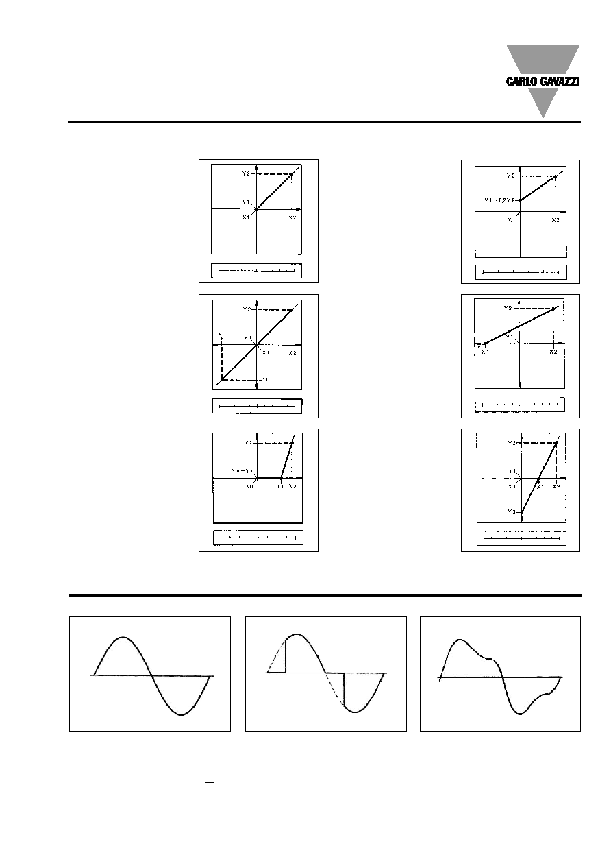
Function Description
Figure A
The sign of measured quant-
ity and output quantity re-
mains the same. The output
quantity is proportional to the
measured quantity.
Input and output scaling capability
Working of the analogue outputs (y) versus input variables (x)
Figure B
The sign of measured quant-
ity and output quantity
changes simultaneously. The
output quantity is proportion-
al to the measured quantity.
Figure C
The sign of measured quant-
ity and output quantity re-
mains the same. On the
range X0...X1, the output
quantity is zero. The range
X1...X2 is delineated on the
entire output range Y0 =
Y1...Y2 and thus presented in
strongly expanded form.
Figure F
The sign of the measured
quantity remains the same,
that of the output quantity
changes as the measured
quantity leaves range X0...X1
and passes to range X1...X2
and vice versa.
Figure E
The sign of the measured
quantity changes but that of
the output quantity remains
the same. The output quant-
ity steadily increases from
value X1 to value X2 of the
measured quantity.
Figure D
The sign of measured quant-
ity and output quantity re-
mains the same. With the
measured quantity being
zero, the output quantity
already has the value
Y1 = 0.2 Y2.
Live zero output.
0 50 A 100 A
0 10 mA 20 mA
-100 kW
0
100 kW
-1 kW
0
1 kW
80 V
100 V
120 V
0 5 mA
10
mA
0 50 A
100
A
4 12 mA
20
mA
-100 kW
0
100 kW
0 10 mA
20 mA
0 50 A
100
A
-1 V
0
1 V
Waveform of the signals that can be measured
Figure G
Sine wave, undistorted
Fundamental content
100%
Harmonic content
0%
A
rms
=
1.1107 | A |
Figure H
Sine wave, indented
Fundamental content
10...100%
Harmonic content
0...90%
Frequency spectrum 3rd to 50th harmonic
Figure I
Sine wave, distorted
Fundamental content
70...90%
Harmonic content
10...30%
Frequency spectrum 3rd to 50th harmonic
Mode of Operation
6
Specifications are subject to change without notice WM3-96DS0303
WM3-96
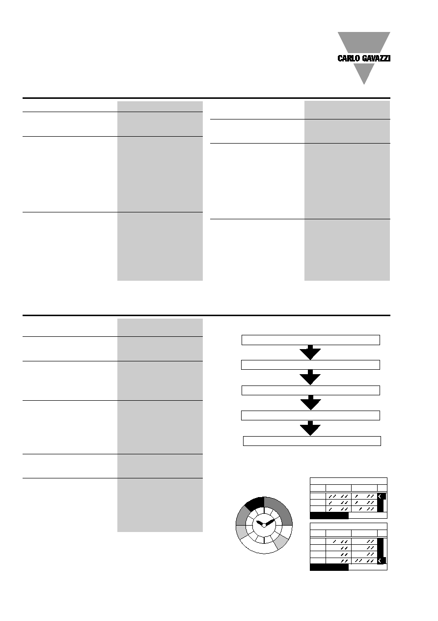
Management concept (multi-time)
(a)
(b)
(c)
Analysis principle
FFT
Harmonic measurement
Current
Up to 50th harmonic
Voltage
Up to 50th harmonic
Type of harmonics
THD (V
L
1)
THD odd (V
L
1)
THD even (V
L
1)
and also for the other phases:
L2, L3.
THD (I
L
1)
THD odd (I
L
1)
THD even (I
L
1)
and also for the other phases:
L2, L3.
Harmonic phase angle
The instrument measures the
angle between the single har-
monic of "V" and the single
harmonic of "I" of the same
order. According to the value
of the electrical angle, it is
possible to know if the distor-
tion is absorbed or generated.
Note: if the system has 3
wires the angle cannot be
measured.
Harmonic details
For every THD page it is pos-
sible to see the harmonic
order.
Display pages
The harmonics content is
displayed as a graph showing
the whole harmonic spectrum.
The information is given also
as numerical information:
THD in % / RMS value
THD odd in % / RMS value
THD even in % / RMS value
single harmonic in % / RMS
value
Others
The harmonic distortion
can be measured in both
2-wire, 3-wire or 4-wire
systems.
Tw: 0.02
Harmonic distortion analysis
Time periods
Selectable: single time,
dual time and multitime
Single time
Number of energy meters
Total: 4 (9-digit)
(no partial meters)
Dual time
Number of energy meters
Total: 4 (9-digit)
Partial: 8 (6-digit)
Time periods
2, programmable within
24 hours
Multi time
Number of energy meters
Total: 4 (9-digit)
Partial: 48 (6-digit)
Time periods
4, programmable
within 24 hours
Time seasons
3, programmable within
12 months
Pulse outputs
Connectable to total and
partial energy meters (Dual
time, Multi time periods)
Energy metering recording
Energy consumption story,
recording of energy metering
by months, oldest data: 2
months before current month.
Recording of total and partial
energy metering
Energy time period management
+Wh, +VArh, ≠Wh, -VArh
max. 4
Time period (24 hours)
max. 3
Season (12 months)
Partial: up to 48 energy meters (axbxc)
Total: up to 4 energy meters ("a" type)
Example of Multi-time energy metering
trf
end
start
WINTER
1
OO:OO O6:OO
2
O6:OO O8:OO
3
O8:OO 1O:OO
TARIFF
1
trf1
24
6
12
18
2
4
8
10
14
16
20
22
trf2
trf2
trf3
trf3
trf4
trf1
trf
WINTER
2
1O:OO 16:OO
3
16:OO 18:OO
4
18:OO 21:OO
TARIFF
1
1
21:OO OO:OO
start end
Specifications are subject to change without notice WM3-96DS0303
7
WM3-96
Variables that can be displayed in case of a three-phase system, 4-wire connection.
No
1st variable
2nd variable
3rd variable
4th variable Note
Selectable
Selectable
Selectable
Selectable
1
V L1
V L2
V L3
V L-N sys
Sys =
2
V L1-2
V L2-3
V L3-1
V L-L sys
Sys =
3
A L1
A L2
A L3
A n
4
W L1
W L2
W L3
W sys
Sys =
5
var L1
var L2
var L3
var sys
Sys =
6
VA L1
VA L2
VA L3
VA sys
Sys =
7
PF L1
PF L2
PF L3
PF sys
8
V L1
A L1
PF L1
W L1
9
V L2
A L2
PF L2
W L2
10
V L3
A L3
PF L3
W L3
11
V L-L sys
PF sys
var sys
W sys
Sys =
12
A n
PF sys
Hz
W sys
Sys =
13
A n dmd
VA dmd
PF avg
W dmd
dmd=demand, avg=average
14
(MAX1)
(MAX2)
(MAX3)
(MAX4)
The MAX value can be one of the
15
(MAX5)
(MAX6)
(MAX7)
(MAX8)
above mentioned (No. 1 to No. 13)
16
(MAX9)
(MAX10)
(MAX11)
(MAX12)
17
(MIN1)
(MIN2)
(MIN3)
(MIN4)
The MIN value can be one of the
18
(MIN5)
(MIN6)
(MIN7)
(MIN8)
above mentioned (No. 1 to No. 13)
19
Histogram FFT V1 (THD, TADo, THDe, Single harmonic)
Only if analysis V1-A1 is activated
20
Histogram FFT A1 (THD, TADo, THDe, Single harmonic)
Only if analysis V1-A1 is activated
21
Histogram FFT V2 (THD, TADo, THDe, Single harmonic)
Only if analysis V2-A2 is activated
22
Histogram FFT A2 (THD, TADo, THDe, Single harmonic)
Only if analysis V2-A2 is activated
23
Histogram FFT V3 (THD, TADo, THDe, Single harmonic)
Only if analysis V3-A3 is activated
24
Histogram FFT A3 (THD, TADo, THDe, Single harmonic)
Only if analysis V3-A3 is activated
25
KWh + TOT
KWh ≠ TOT
Kvar+ TOT
Kvar≠ TOT
26
KWh+
KWh≠
Kvar+
Kvar≠
Partial energy meters
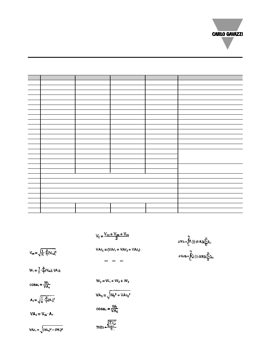
Display pages
Used Calculation Formulas
Formulas being used for
single-phase measurements
Instantaneous effective voltage
Instantaneous active power
Instantaneous power factor
Instantaneous effective current
Instantaneous apparent power
Instantaneous reactive power
Formulas being used for 3-phase measurements
Equivalent three-phase voltage
Three-phase reactive power
Neutral current
Three-phase active power
Three-phase apparent power
Equivalent three-phase power factor
(TPF)
Total harmonic distortion
Harmonic values:
THDi-THD of parameter T at phase i
Tn,i - value of parameter T at the n'th
harmonic of phase i
Energy metering
kWh
i
= total consumed active energy
at phase i
kVArh
i
= total consumed reactive
energy at phase i
P
i
(t) = total RMS active power at
phase i of time t
Q
i
(t) = total RMS reactive power at
phase i of time t
t
1
t
2
= starting and ending time points
of consumption recording
P
n,i
= total RMS active power at
phase i of discrete time n
Q
n,i
= total RMS reactive power at
phase i of discrete time n
t = time interval between two suc-
cessive power consumptions
n1, n2 = starting and ending discrete
time points of consumption recording
An = A
L1
+A
L2
+A
L3

8
Specifications are subject to change without notice WM3-96DS0303
WM3-96
List of the variables that can be connected to:
∑ max/min variable detection;
∑ analogue outputs;
∑ alarm outputs.
No
Variable
1-phase
3-ph. + N
3-ph. + N
3-ph.
3-ph.
Note
Sys.
Bal. Sys.
Unbal. Sys.
Bal. Sys.
Unbal. Sys.
1
V L1
o
x
x
o
o
2
V L2
o
x
x
o
o
3
V L3
o
x
x
o
o
4
V L-N sys
o
x
x
o
o
Sys =
5
V L1-2
x
x
x
x
x
6
V L2-3
o
x
x
x
x
7
V L3-1
o
x
x
x
x
8
V L-L sys
o
x
x
x
x
Sys =
9
A L1
x
x
x
x
x
10
A L2
o
x
x
x
x
11
A L3
o
x
x
x
x
12
A n
o
x
x
o
o
Neutral current
13
W L1
x
x
x
o
o
14
W L2
o
x
x
o
o
15
W L3
o
x
x
o
o
16
W sys
o
x
x
x
x
Sys =
17
var L1
x
x
x
o
o
18
var L2
o
x
x
o
o
19
var L3
o
x
x
o
o
20
var sys
o
x
x
x
x
Sys =
21
VA L1
x
x
x
o
o
22
VA L2
o
x
x
o
o
23
VA L3
o
x
x
o
o
24
VA sys
o
x
x
x
x
Sys =
25
PF L1
x
x
x
o
o
26
PF L2
o
x
x
o
o
27
PF L3
o
x
x
o
o
28
PF sys
o
x
x
x
x
Sys =
29
Hz
x
x
x
x
x
30
THD V1
x
x
x
x
x
if FFT V1-A1 is activated
31
THDo V1
x
x
x
x
x
if FFT V1-A1 is activated
32
THDe V1
x
x
x
x
x
if FFT V1-A1 is activated
33
THD V2
o
x
x
x
x
if FFT V2-A2 is activated
34
THDo V2
o
x
x
x
x
if FFT V2-A2 is activated
35
THDe V2
o
x
x
x
x
if FFT V2-A2 is activated
36
THD V3
o
x
x
x
x
if FFT V3-A3 is activated
37
THDo V3
o
x
x
x
x
if FFT V3-A3 is activated
38
THDe V3
o
x
x
x
x
if FFT V3-A3 is activated
39
THD A1
x
x
x
x
x
if FFT V1-A1 is activated
40
THDo A1
x
x
x
x
x
if FFT V1-A1 is activated
41
THDe A1
x
x
x
x
x
if FFT V1-A1 is activated
42
THD A2
o
x
x
x
x
if FFT V2-A2 is activated
43
THDo A2
o
x
x
x
x
if FFT V2-A2 is activated
44
THDe A2
o
x
x
x
x
if FFT V2-A2 is activated
45
THD A3
o
x
x
x
x
if FFT V3-A3 is activated
46
THDo A3
o
x
x
x
x
if FFT V3-A3 is activated
47
THDe A3
o
x
x
x
x
if FFT V3-A3 is activated
48
A n dmd
x
x
x
x
x
Integration time programmable
from 1 to 30 minutes
49
VA dmd
x
x
x
x
x
Integration time prog. from 1 to 30 min.
50
PF avg
x
x
x
x
x
Integration time prog. from 1 to 30 min.
51
W dmd
x
x
x
x
x
Integration time prog. from 1 to 30 min.
52
ASY
o
x
x
x
x
Integration time prog. from 1 to 30 min.
Note: (x) stands for an "available" variable, (o) stands for a "not-available" variable.

Specifications are subject to change without notice WM3-96DS0303
9
WM3-96
Basic unit
Slot A Slot B Slot C Slot D
Single analogue output
Dual analogue output
RS485 input/output
Single relay output (*)
Single open collector out (*)
Dual relay output (*)
Dual open coll. out (*)
4 open coll. output (*)
3 digital inputs
Wiring Diagrams
Single phase input connections
CT connection
Direct connection
CT and VT connection
Fig. 2
Fig. 1
Fig. 3
Type
N. of
Ordering
channels
code
WM3-96 base
AD 1016
WM3-96 N2 METASYS base
AD 1016N2
AV5.3 measuring inputs
AQ 1018
AV7.3 measuring inputs
AQ 1019
18-60VAC/DC power supply
AP1021
90-260VAC/DC power supply
AP1020
20mADC analogue output
1
AO1050
10VDC analogue output
1
AO1051
±5mADC analogue output
1
AO1052
±10mADC analogue output
1
AO1053
±20mADC analogue output
1
AO1054
±1VDC analogue output
1
AO1055
±5VDC analogue output
1
AO1056
±10VDC analogue output
1
AO1057
20mADC analogue output
2
AO1026
10VDC analogue output
2
AO1027
±5mADC analogue output
2
AO1028
±10mADC analogue output
2
AO1029
±20mADC analogue output
2
AO1030
±1VDC analogue output
2
AO1031
±5VDC analogue output
2
AO1032
±10VDC analogue output
2
AO1033
RS485 output
1
AR1034
Relay output
1
AO1058
Relay output
2
AO1035
Open collector output
1
AO1059
Open collector output
2
AO1036
Open collector output
4
AO1037
Digital inputs
3
AQ1038
RS232 output + RTC (1)
1
AR1039
(1)
The RS232 communication port works as
alternative of the RS485 module.
N2-Open Metasys protocol
full compatibility (available on
request).
(*) alarm or pulse
The available modules
The possible module combinations
Basic unit
Slot E
RS232 input/output + RTC

10
Specifications are subject to change without notice WM3-96DS0303
WM3-96
CT connection (4-wire system)
Direct connection (4-wire system)
CT and VT connection (4-wire system)
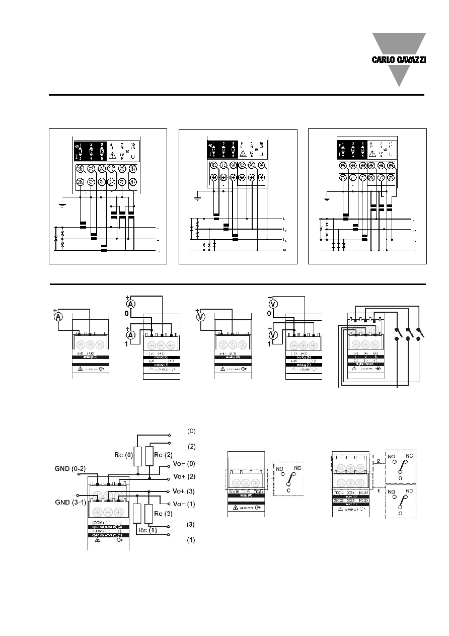
Wiring Diagrams (cont.)
Three-phase, 3-wire ARON input connections - Unbalanced loads
CT connection (3-wire system)
CT and VT connection (3-wire system)
Fig. 7
Fig. 8
Fig. 9
Fig. 10
Fig. 11
Three-phase wire input connections - Balanced loads
CT connection (3-wire system)
Direct connection (3-wire system)
CT and VT connection (3-wire system)
Fig. 4
Fig. 5
Fig. 6
Fig. 12
CT and VT connection (3-wire system)
Specifications are subject to change without notice WM3-96DS0303
11
WM3-96
CT connection (4-wire system)
CT connection (3-wire system)
CT and VT connection (4-wire system)
Fig. 13
Fig. 14
Fig. 15
Wiring Diagrams (cont.)
Three-phase four-wire input connections - Unbalanced load
Three-phase three-wire input connections
Unbalanced load
Wiring diagrams (optional modules)
4 open collector outputs: The load resistance (Rc) must be designed so that the closed contact current is lower than 100mA;
the VDC voltage must be lower than or equal to 30V.
VDC: power supply voltage output. Vo+: positive output contact (open collector transistor). GND: ground output contact (open
collector transistor).
1 analogue
output (mA)
1 relay output
1 analogue
output (V)
2 analogue
outputs (mA)
2 relay outputs
2 analogue
outputs (V)
3 digital inputs
VDC
VDC
VDC
VDC
12
Specifications are subject to change without notice WM3-96DS0303
WM3-96
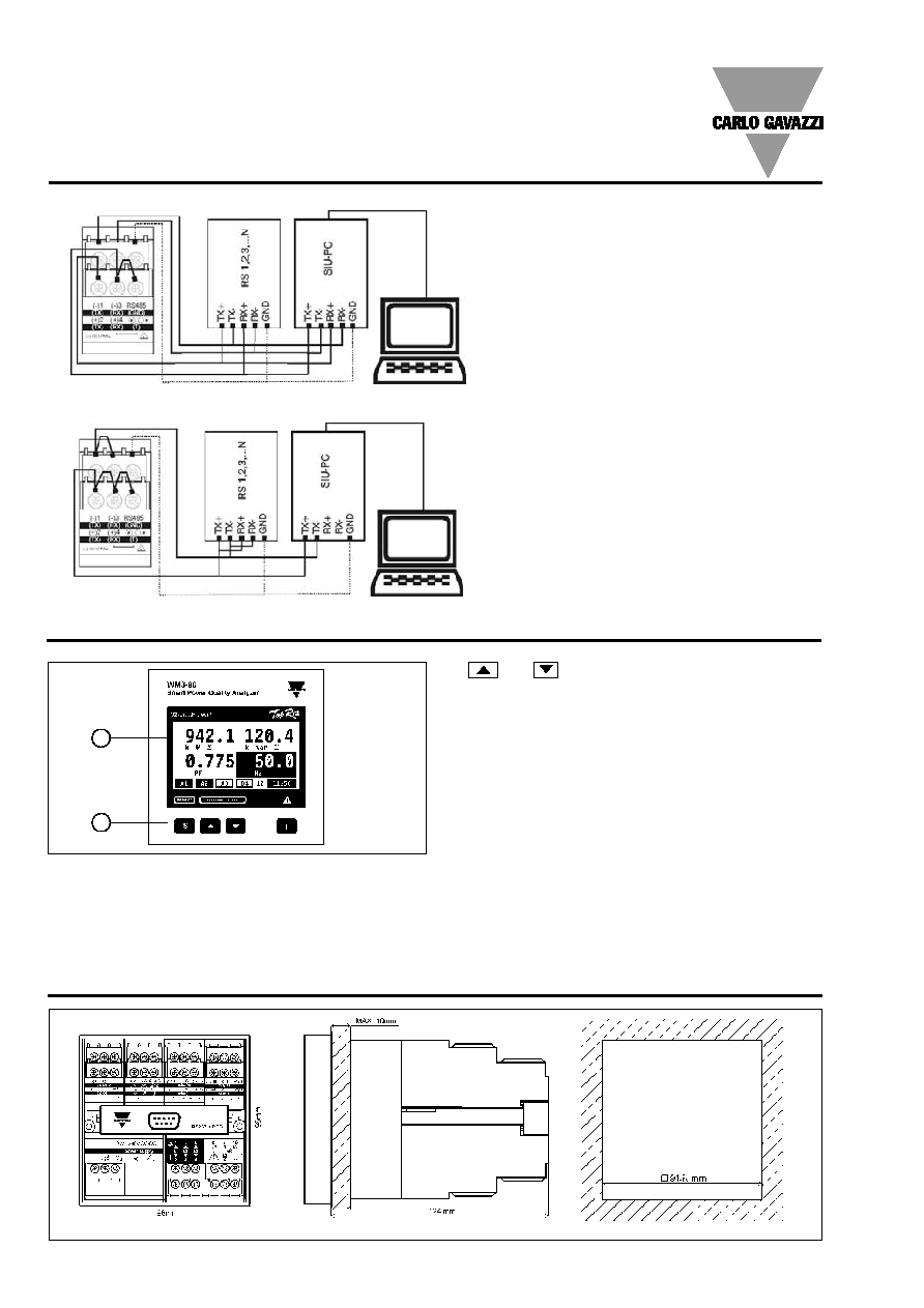
Dimensions
Front Panel Description
1
- for value programming/function selection, page scrolling
- "F" for special functions
2. Display
Istantaneous measurements:
- 4-digit (maximum read-out 9999)
Energies:
- 9-digit (maximum read-out 999999999).
Alphanumeric indication by means of LCD display for:
- Displaying the configuration parameters
- All the measured variables.
1. Key-pad
Set-up and programming procedures are easily controlled
by the 4 pushbuttons.
- "S" for enter programming phase and password
confirmation,
2
Wiring diagrams (optional modules, cont.)
RS422/485 4-wires connection:
additional
devices provided with RS422/485 (that is RS 1, 2,
3...N) are connected in parallel.
The termination of the serial output is carried out
only on the last instrument of the network, by
means of a jumper between (Rx+) and (T).
RS422/485 2-wires connection:
additional
devices provided with RS422/485 (that is RS 1, 2,
3...N) are connected in parallel.
The termination of the serial output is carried out
only on the last instrument of the network, by
means of a jumper between (Rx+) and (T).
Specifications are subject to change without notice WM3-96DS0303
13
WM3-96
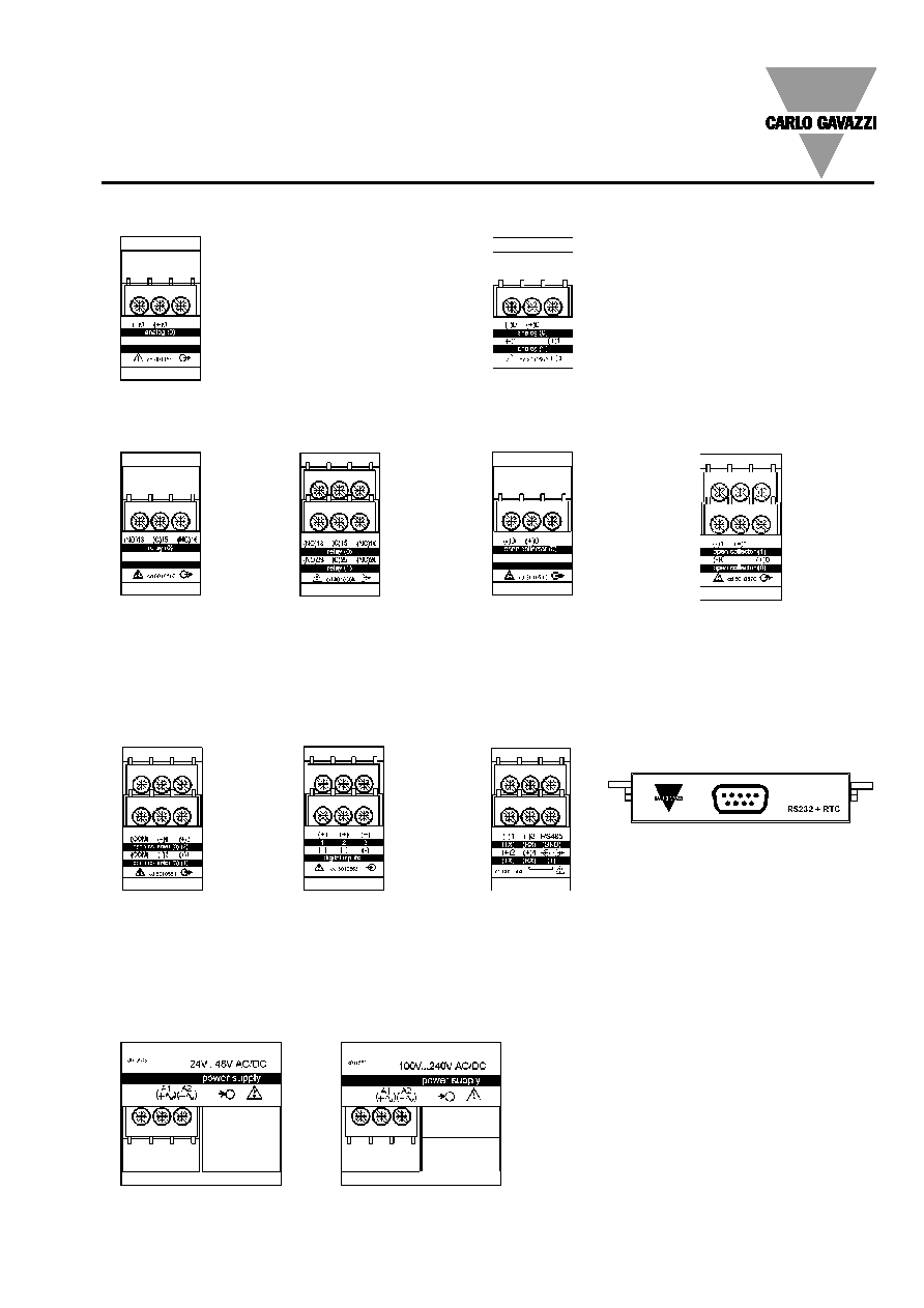
Terminal boards
AP1021
18-60VAC/DC power supply
AP1020
90-260 VAC/DC power supply
AO1050
(20mADC)
AO1051
(10VDC)
AO1052
(±5mADC)
AO1053
(±10mADC)
AO1054
(±20mADC)
AO1055
(±1VDC)
AO1056
(±5VDC)
AO1057
(±10VDC)
AO1026
(20mADC)
AO1027
(10VDC)
AO1028
(±5mADC)
AO1029
(±10mADC)
AO1030
(±20mADC)
AO1031
(±1VDC)
AO1032
(±5VDC)
AO1033
(±10VDC)
AR1034
RS485 port
AO1035
Dual relay output
AO1059
Single open collector
output
AO1036
Dual open collector
output
AO1058
Single relay output
AQ1038
3 Digital inputs
AR1039
RS232 port + RTC
Single analogue output modules
Dual analogue outputs
Digital output modules
Other input/output modules
Power supply modules
AO1037
4 open collector
outputs