Specifications are subject to change without notice (03.01.03)
1
Rated operating dist. (S
n
)
CA18GLF08
3 to 8 mm
factory set at 8 mm
Sensitivity
Adj. 270∞ turn pot. meter
Effective operation dist. (S
r
)
0.9 x S
n
S
r
1.1 x S
n
Usable operation dist. (S
u
)
0.8 x S
r
S
n
1.2 x S
r
Repeat accuracy (R)
5%
Hysteresis (H)
4 to 20% of sensing distance
Rated operational volt. (U
B
)
10 to 40 VDC
(ripple included)
Ripple
10%
Rated operational current (I
e
)
Continuous
200 mA
No-load supply current (I
o
)
10 mA
Voltage drop (U
d
)
2.5 VDC at max. load
Protection
Reverse polarity,
short-circuit, transients
Frequency of operating
cycles (f)
30 Hz
Indication for output ON
LED, yellow
Environment
Degree of protection
IP 67 (Nema 1, 3, 4, 6, 13)
Temperature
Operating temperature
-25∞ to +60∞C ( -13∞ to +176∞F)
Storage temperature
-40∞ to +65∞C (-40∞ to +185∞F)
Housing material
Body, front, nuts
Grey PVC
Connection
Cable
Grey, 2 m, 4 x 0.34 mm
2
Oil proof PVC
Weight
110 g
CE-marking
Yes
Type Selection
Product Description
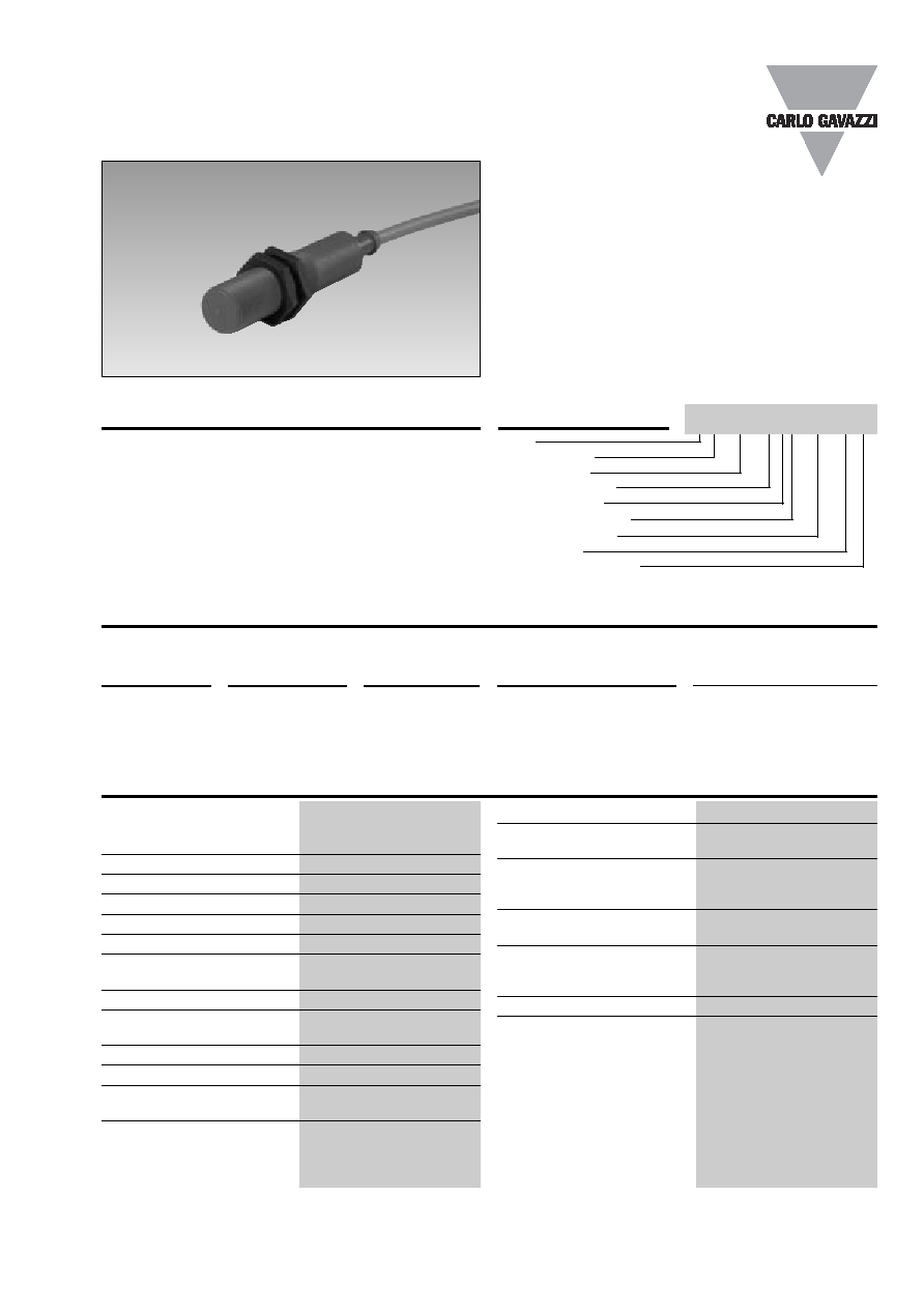
Proximity Sensors Capacitive
PVC Housing
Type CA, M18, DC
∑ Featuring
TRIPLESHIELDTM sensor protection
∑ Adjustable sensing distance 3-8 mm
∑ Rated operational voltage: 10-40 VDC
∑ Output: DC 200 mA, NPN or PNP
∑ Make and break switching function
∑ LED indication
∑ High noise immunity
∑ Flush types
∑ Cable versions
Capacitive proximity switches
with sensing distance of 8 mm
flush mounted in metal. 4-wire
DC output with both make
(NO) and break (NC) switching.
Grey M18 PVC housing with
2 m PVC cable. Ideal for use
in level applications in che-
mical, semi-conductor and
food & beverage industries.
Housing
Rated
Mounting
Ordering no.
Ordering no.
diameter
operating
Transistor NPN
Transistor PNP
dist. (S
n
)
1)
Make & break switching
Make & break switching
M18
8 mm
Flush (built-in)
CA18GLF08NA
CA18GLF08PA
1)
Object: Grounded steel plate
Specifications
TRIPLESHIELD
TM
Type
Housing style
Housing size
Housing material
Housing length
Detection principle
Sensing distance
Output type
Output configuration
Ordering Key
CA 18 GLF 08 NA

2
Specifications are subject to change without notice (03.01.03)
Delivery Contents
Wiring Diagrams
CA, M18, DC
NPN
PNP
3 BU
2 WH
4 BK
1 BN
1 BN
2 WH
4 BK
3 BU
∑ Capacitive switch: CA18GL...
∑ Screw driver
∑ 2 nuts
∑ Packaging: Cardboard box
∑ Installation & Adjustment Guide
Max.
Min.
Sensitivity
The environments in which
capacitive sensors are install-
ed can often be unstable re-
garding temperature, humidity,
object distance and industrial
(noise) interference. Because
of this, Carlo Gavazzi offers as
standard features in all TRIP-
LESHIELDTM capacitive sen-
sors a user-friendly sensitivity
adjustment instead of having
a fixed sensing range, extend-
ed sensing range to accom-
modate mechanically demand-
ing areas, temperature stability
to ensure minimum need for
adjusting sensitivity if temper-
ature varies and high immunity
to electromagnetic interfer-
ence (EMI).
Note:
Sensors are factory set (de-
fault) to maximum rated sens-
ing range.
Adjustment Guide
Installation Hints
Capacitive sensors have the
unique ability to detect almost
all materials, either in liquid or
solid form. Capacitive sen-
sors can detect metallic as
well as non-metallic objects,
however, their traditional use
is for non-metallic materials
such as:
∑ Plastic Industry
Resins, regrinds or mould-
ed products.
∑ Chemical Industry
Cleansers, fertilisers, liquid
soaps, corrosives and
petrochemicals.
∑ Wood Industry
Saw dust, paper products,
door and window frames.
∑ Ceramic & Glass
Industry
Raw material, clay or finish-
ed products, bottles.
∑ Semi-conductor Industry
∑ Food & Beverage
Industry
∑ Packaging Industry
Package inspection for
level or contents, dry
goods, fruits and vegeta-
bles, dairy products.
Materials are detected due to
their dielectric constant. The
bigger the size of an object,
the higher the density of ma-
terial, the better or easier it is
to detect the object. Nominal
sensing distance for a capaci-
tive sensor is referenced to a
grounded metal plate (ST37).
For additional information re-
garding dielectric ratings of
materials please refer to
Technical Information.
Dimensions
Relief of cable strain
Protection of the sensing face
Switch mounted on mobile carrier
To avoid interference from inductive voltage/
current peaks, separate the prox. switch pow-
er cables from any other power cables, e.g.
motor, contactor or solenoid cables
Incorrect
Correct
The cable should not be pulled
A proximity switch should not serve as
mechanical stop
Any repetitive flexing of the
cable should be avoided