Specifications are subject to change without notice (03.10.2006)
1
Housing dimensions
Rated operating distance
Ordering no.
Ordering no.
(S
n
)
NPN, Cable
PNP, Cable
28x46x5,5 mm
10 mm
CD46CNC10NP
CD46CNC10PP
Ordering Key
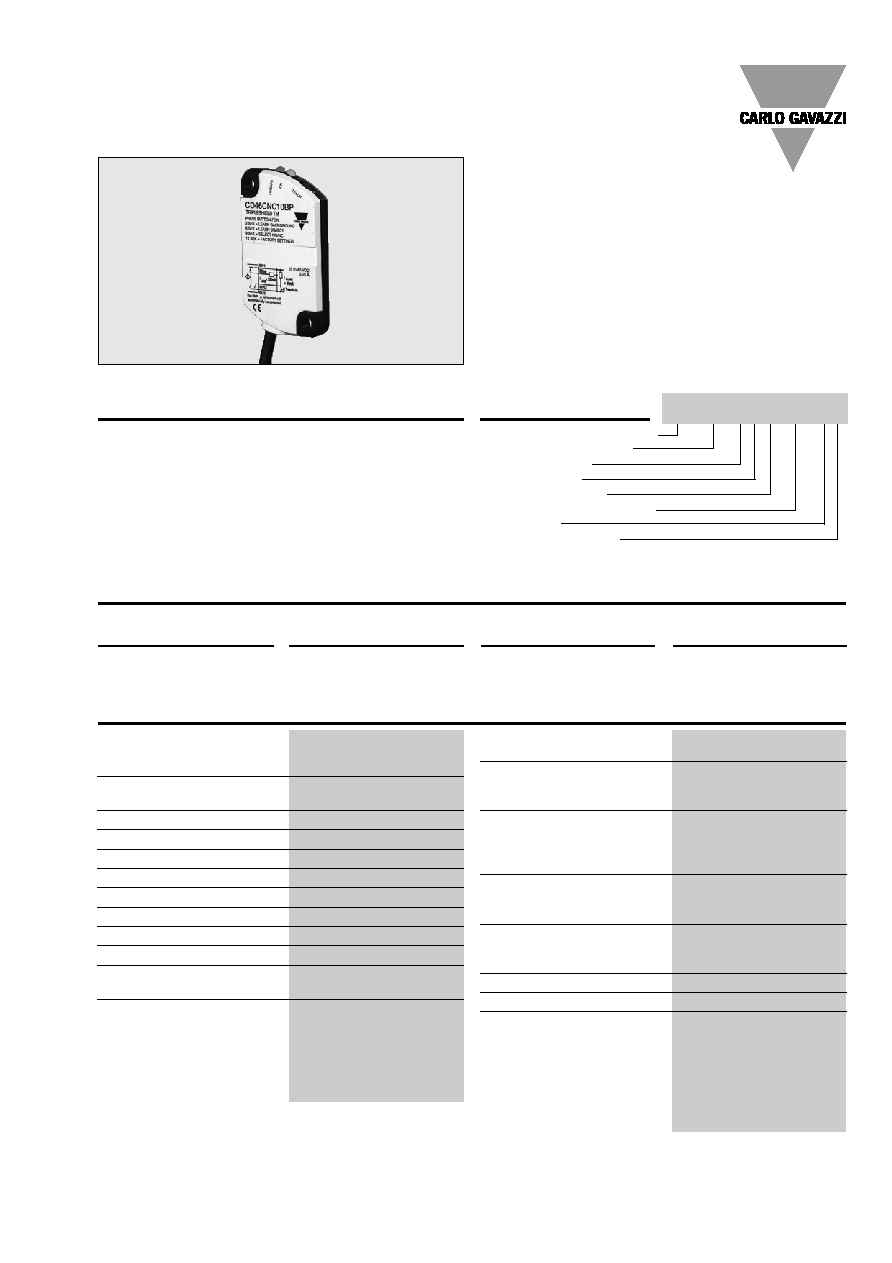
Product Description
Proximity Sensors Capacitive
Thermoplastic Polyester Housing
Types CD46, DC, Teach-in
∑ Thin Profile Capacitive Level Sensor
∑ Featuring
TRIPLESHIELDTM Sensor Protection
∑ Sensing distance: 1 - 10 mm
∑ Teach-in of sensing distance via push-button or
wire-input
∑ Selectable make or break switching by means of
Teach-in function
∑ Protection: Short-circuit, transients and reverse polarity
∑ Alarm output
∑ 5 years of warranty
∑ Alarm output when operating current > 250 mA
Capacitive prox im ity switch
Housing hight (mm)
Housing material
Housing length
Detection principle
Rated operating dist. (mm)
Output type
Output configuration
Type Selection
Capacitive proximity level
switch with a sensing dis-
tance of 10 mm non-flush
mounted. The switching
points can be altered by
means of the Teach-in func-
tion. 3-wire DC output with
selectable make (NO) or
break (NC) switching and
NPN Alarm. Grey/black
polyester housing with 2 m
PVC cable.
Designed for front, pipe or
plane mounting.
TRIPLESHIELD
TM
CD 46 CNC 10 NP
Sensing range (S
d
)
1 - 10 mm
factory set at 10 mm
Sensitivity
Adjustable (Teach-in)
Effective operating dist. (S
r
)
0.9 x S
n
S
r
1.1 x S
n
Usable operating dist. (S
u
)
0.8 x S
r
S
u
1.2 x S
r
Repeat accuracy (R)
5%
Hysteresis (H)
Depending on Teach-in
Rated operational volt. (U
B
)
10 to 30 VDC (ripple incl.)
Ripple
10%
Rated operational current (I
e
) 200 mA (continuous)
No-load supply current (I
o
)
12 mA
Voltage drop (U
d
)
2.5 VDC @ max. load
Protection
Short-circuit, reverse
polarity, transients
TRIPLESHIELD
TM
protection-EMC
IEC 1000-4-2/EN 61000-4-2
30 kV
IEC 1000-4-3/EN 61000-4-3
> 10 V/m
IEC 1000-4-4/EN 61000-4-4
3 kV
IEC 1000-4-6/EN 61000-4-6
> 10 V
rms
*
Frequency of operating
cycles (f)
10 Hz
Indication
For output ON
LED, yellow
For safe/unsafe
LED, green
Environment
Degree of protection
IP 68
Operating temperature
-20∞ to +80∞C ( -4∞ to +176∞F)
Storage temperature
-40∞ to +85∞C (-40∞ to +185∞F)
Housing material
Body
Grey/black PBT
Button and Lightguide
TPE-U
Connection
Cable
Black, 2 m, 4 x 0.14 mm
2
Oil proof, PVC
Weight
50 g
Approvals
UL, CSA
CE-marking
Yes
Specifications
* Not observed around the oscillator frequency: 0.3 - 1.6 MHz

28
5,5
46
2
Specifications are subject to change without notice (03.10.2006)
CD46, DC, Teach-in
The environments in which
capacitive sensors are install -
ed can often be un
stable re -
garding temperature, humi dity ,
object distance and industrial
(noise) interference. Because
of this, Carlo Ga
vazzi offers
as standard features in all
TRIP LESHIELDTM capacitive
sensors a user-friendly sensi-
tivity adjustment instead of
having a fixed sensing range,
extend ed sen
sing range to
accommodate mechanically
demand ing are as, temperature
stability to en
sure minimum
need for adjusting sensitivity if
temperature varies and high
immunity to elec
tro magnetic
interference (EMI).
Adjustment
Installation Hints
Capacitive sensors have the
unique ability to detect al
-
most all materials, either in li -
quid or solid form. Capa ci tive
sensors can detect metallic
as well as non-metallic ob
-
jects, how ever, their tradition-
al use is for non-metallic
materials such as:
∑ Plastics Industry
Resins, regrinds or mould -
ed products.
∑ Chemical Industry
Cleansers, fertilisers, liquid
soaps, corrosives and pe -
t ro chemicals.
∑ Wood Industry
Saw dust, paper products,
door and window frames.
∑ Ceramic & Glass
Industry
Raw material, clay or
finish ed products, bottles.
∑ Packaging Industry
Package inspection for level
or contents, dry goods,
fruits and vegetables, dairy
products.
Materials are detected due to
their dielectric constant. The
bigger the size of an object,
the higher the density of ma -
terial, the better or easier it is
to detect the object. Nominal
sensing di stan ce for a capaci-
tive sensor is refe r enced to a
grounded me tal plate (ST37).
For addi
tional information
regarding di
elec tric ratings
of materials please re
fer to
Technical Information.
Dimensions
Relief of cable strain
Protection of the sensing face
Switch mounted on mobile carrier
To avoid interference from inductive voltage/
current peaks, separate the prox. switch pow-
er cables from any other power cables, e.g.
motor, contactor or solenoid cables
Not correct
Correct
The cable should not be pulled
A proximity switch should not serve as
mechanical stop
Any repetitive flexing of the
cable should be avoided
Delivery Contents
∑ Capacitive switch
∑ Packaging: Cardboard box
∑ Installation & Adjustment Guide
Specifications are subject to change without notice (03.10.2006)
3
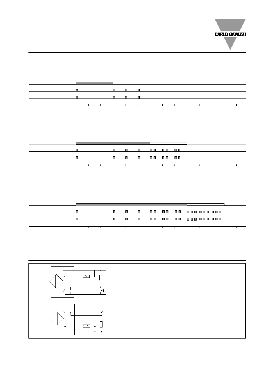
Teach-in Guide
Adjustment - Background
No target present
Push-button
LED - Green
LED - Yellow
Time (sec)
Press push-button >3 seconds until LED¥s are flashing one time per second. The background will be calibrated when the
push-button is released during the following 3 seconds
Adjustment - Object
Target present
Push-button
LED - Green
LED - Yellow
Time (sec)
Press push-button >6 seconds until LED¥s are flashing two times per second. The object will be calibrated when the push-
button is released during the following 3 seconds
Adjustment - NO - NC
Push-button
LED - Green
LED - Yellow
Time (sec)
0 1 2 3 4 5 6 7 8 9 10 11 12 13
Press push-button >9 sec. until LED¥s are flashing three times per second. The status of NO-NC will toggle when the push-
button is released during the following 3 seconds
Wiring Diagrams
By means of the Teach-in wire, the functions described
in the Teach-in Guide can be setup.
It is possible to Teach-in more sensors at the same time
by connecting the WH-wires in parallel to the common "-
" supply.
(#): Plug connections
Important NPN: If alarm output (WH-wire) is unused, it
has to be terminated to +supply
Important PNP: If alarm output (WH-wire) is unused, it
has to be terminated to ˜supply
0 1 2 3 4 5 6 7 8 9 10 11 12 13
0 1 2 3 4 5 6 7 8 9 10 11 12 13
Releasing the push-button after 12 sec. returns the sensor to factory settings.
CD46, DC, Teach-in
BN+
BK
WH
BU-
I
LOAD
<200mA
I
ALARM
<20mA
Teach-in
BN+
BK
WH
BU-
I
LOAD
<200mA
I
ALARM
<20mA
Teach-in
NPN
PNP