Specifications are subject to change without notice (08.12.2005)
1
Mounting
Relay
Ordering no.
Ordering no.
Ordering no.
Supply: 24 VAC/DC
Supply: 115 VAC
Supply: 230 VAC
DIN-rail DPDT
CLD2ET1CM24
CLD2ET1C115
CLD2ET1C230
11-p circular plug
CLP2ET1CM24
CLP2ET1C115
CLP2ET1C230
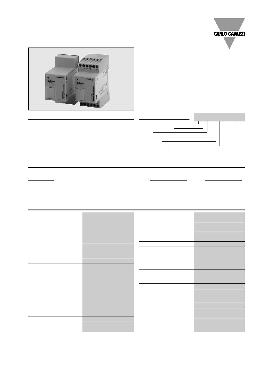
Conductive Sensors
2-point level controller
Type CL with teach-in
∑ Conductive level controller
∑ Teach-in of sensitivity ≠ operating resistance from
220 to 220K
∑ For filling or emptying applications
∑ Low-voltage AC electrodes
∑ Easy installation on DIN rails or with 11 pin circular
plug
∑ Rated operational voltage:
24 VAC/DC, 115 VAC or 230 VAC
∑ Output 2x5A/250 VAC DPDT relay
∑ LED indication for: Calibration, faulty operation and
relay status
Ordering Key
Product Description
Max./min. control of charging/
discharging. The sensitivity is
adjustable by means of the
teach-in function.
2 X 5A DPDT relay output.
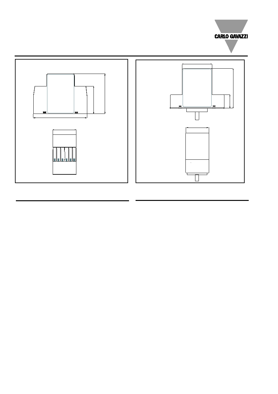
Type
DIN rail mounting
Inputs
Function
Adjustment
Outputs
Relay versions
Power supply
µ-Processor based level
controller for liquids with a
wide sensitivity range (like
sewage water, chemicals, salt
water etc.).
Type Selection
Specifications
Rated operational voltage (U
B
)
Pin 2 & 10
230
195 to 265 VAC, 45 to 65 Hz
115
98 to 132 VAC, 45 to 65 Hz
924
19.2 to 28.8 VAC/DC
Rated insulation voltage
<2.0 kVAC (rms)
Rated impulse withstand
voltage
4 kV (1.2/50 µs) (line/neutral)
Rated operational power
AC supply
5 VA
AC/DC supply
5 VA / 5 W
Delay on operate (t
V
)
< 300 mS
Outputs
Rated insulation voltage
250 VAC (rms) (cont./elec.)
Relay Rating (AgCdO)
µ (micro gap)
Resistive loads
AC1
5 A / 250 VAC (2500 VA)
DC1
1 A / 250 VDC (250 W)
or
5 A 25 VDC (250 W)
Small induc. Loads
AC11
0,4 A 250 VAC
DC13
0,4 A / 30 VDC
Mechanical life (typical)
30 x 106 operations
@ 18'000 imp/h
Electrical life (typical)
AC1
> 250'000 operations
Level probe supply
Max. 12 VAC
Level probe current
Max. 2.5 mA
Sensitivity
220 to 220K
Factory preset: 47K
Dielectric voltage
>2.0 KVAC (rms)
(contacts / electronics)
Rated impulse withstand volt.
4 kV (1.2/50 µS) (contacts /
electronics) (IEC 664)
Operating frequency (f)
Relay output
1 HZ
Response time
1 s (3.5 s with filter)
Environment
Overvoltage category
III (IEC 60664)
Degree of protection
IP 20 /IEC 60529, 60947-1)
Pollution degree
2 (IEC 60664/60664A,
60947-1)
Temperature
Operating
-20∫ to +70∫C (-4∫ to + 158∫)
Storage
-50∫ to +85∫C (-58∫ to +185∫F)
Housing material
NORYL SE1, light grey
Weight
AC supply
200 g
AC/DC supply
125 g
Approvals
UL508, CSA
CE marking
Yes
CLD2ET1CM24
2
Specifications are subject to change without notice (08.12.2005)
Connection cable
2, 3, or 4 conductor PVC
cable, normally screened.
Cable length: max. 100 m.
The resistance between the
cores and the ground must
be at least 220k. Normally, it
is recommended to use a
screened cable between
probe and controller, e.g.
where the cable is placed in
parallel to the load cables
(mains). The screen has to be
connected to Y3 (reference).
DIP-switch setting
Select the needed function
on the DIP-switches, so that
the desirable application
occurs. Press the push-
button in front of the con-
troller shortly, until the green
LED flashes once. The DIP-
switch setting will now be
read by the controller.
Teach-in:
Make sure that the reference
electrode and one of the
other electrodes are in con-
tact with the liquid ≠
approximately 1 cm. Press
the "teach" pushbutton at
the front of the controller for
approximately 2 seconds,
until the green LED turns
OFF. The controller will now
auto-adjust itself according
to the resistance of the
measuring liquid. If the
resistance of the liquid is
outside the maximum range
handled by the controller,
the green LED will flash
quickly for a period of 2
seconds, indicating a wrong
teach-in.
Filter
The signal delay is
selectable from 1 second or
3 seconds, and works for
the on/off switching of the
output relays.
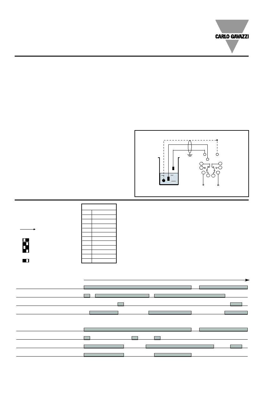
Example 1
The diagram shows the level
control connected as max.
Mode of Operation
CLD2ET1CM24
and min. control. The relays
react to the low alternating
current created when the
electrodes are in contact
with the liquid.
The reference (Ref) must be
connected to the container
or if the container consists
of a non-conductive material,
to an additional electrode.
(To be connected to pin Y3).
(In the diagram this electrode
is shown by the dotted line).
Function: Charge or Discharge
The Controller can be used as a
minimum-maximum control for
one system.
Y2
Y1
Y3
REF
Lo
Hi
Power Supply
Charging or discharging
12
14
A1
11 21
24
A2
22
Charging
Power supply
LO electrode in liquid
HI electrode in liquid
Relay on pumping contact (make)
Discharging
Power supply
HI electrode in liquid
LO electrode in liquid
Relay on pumping contact (make)
Time
X-REFERENCE
TERM
PLUG
Y1
6
Y2
5
Y3
7
22
8
A1
2
A2
10
11
1
12
4
14
3
21
11
24
9
Example 1
(Din-rail)
DIP switches
ON
1 Discharge
1 Charge
2 Filter
off
2 Filter
on
ON
Specifications are subject to change without notice (08.12.2005)
3
DIP switches
ON
1 Discharge
1 Charge
2 Filter
off
2 Filter
on
ON
Dip Switch Settings
Operating Schedule
Situation
Read DIP-switch
setting
Teach-in
Failure
indication
The following schedule provides an overview of the setup and failure situations
Condition
The DIP-switch setting has
to match one of the
descriptions written in
"mode of operation"
Fill the tank with the liquid to
be measured until the
second longest electrode is
immersed approx. 1cm
The Green lamp is
flashing fast for approx. 2
seconds after a teach-in
operation
Action
Press the Teach-button in
front of the controller shortly
until the green control lamp
turns off. Release the teach
button immediately
Press the Teach button in
front of the controller for
approx. 2 seconds until the
green control lamp turn off
continuously. Release the
teach button
Control the electrode for
short-cut connections.
Control that the resistance of
the measured liquid is within
the specified range
Green Control lamp
Teach button
Green lamp
Teach button
Green lamp
Teach button
Green lamp
CLD2ET1CM24
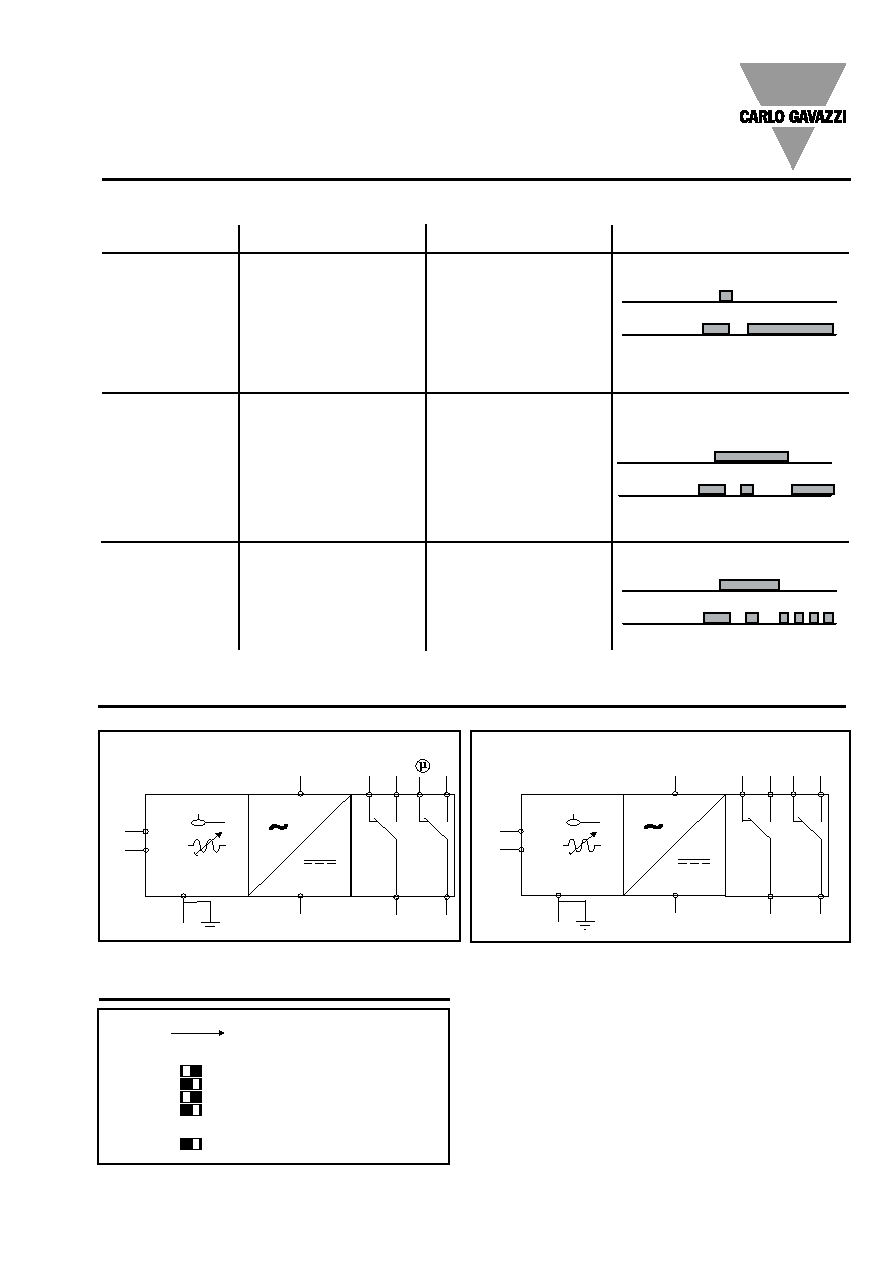
Wiring Diagram
(PE)
(PE)
A1
A2
21
24
12
11
14
Y1
Y2
Y3
Lo
Hi
Ref
22
(PE)
(PE)
2
10
11
9
1
3
6
5
7
Lo
Hi
Ref
4
8
Plug version
Din-rail version