Du line
Æ
Fieldbus
Installationbus
Specifications are subject to change without notice (28.09.99)
1
Dupline
Æ
is a registered trademark. A product of the CARLO GAVAZZI Group
Supply
Ordering no.
Ordering no.
No. of channels selectable
No of channels selectable
1, 2 or 3 sequences
1, 2 or 3 sequences
24 VAC
FPD 1901 024
D 3490 0000 024
120 VAC
FPD 1901 120
D 3490 0000 115
220 VAC
FPD 1901 220
D 3490 0000 230
15 to 30 VDC
FPD 1901 824
D 3490 0000 824
Code modules:
1 sequence
FMK 8 to FMK 128
FMK 8 to FMK 128
2 sequences
FMK 16-2 to 128-2
FMK 16-2 to 128-2
3 sequences
FMK 16-3 to 128-3
FMK 16-3 to 128-3
∑ Generates 8, 16, 32, 64 or 128 channels
∑ Number of sequences selectable
∑ Quartz-controlled oscillator
∑ Cable compensation
∑ Stop-function
∑ Plug-in type (FPD)
∑ DIN-rail mounting type (D3490) (EN 50022)
∑ LED-indication for supply
∑ LED-indication for supply and Dupline
Æ
carrier
∑ AC or DC power supply
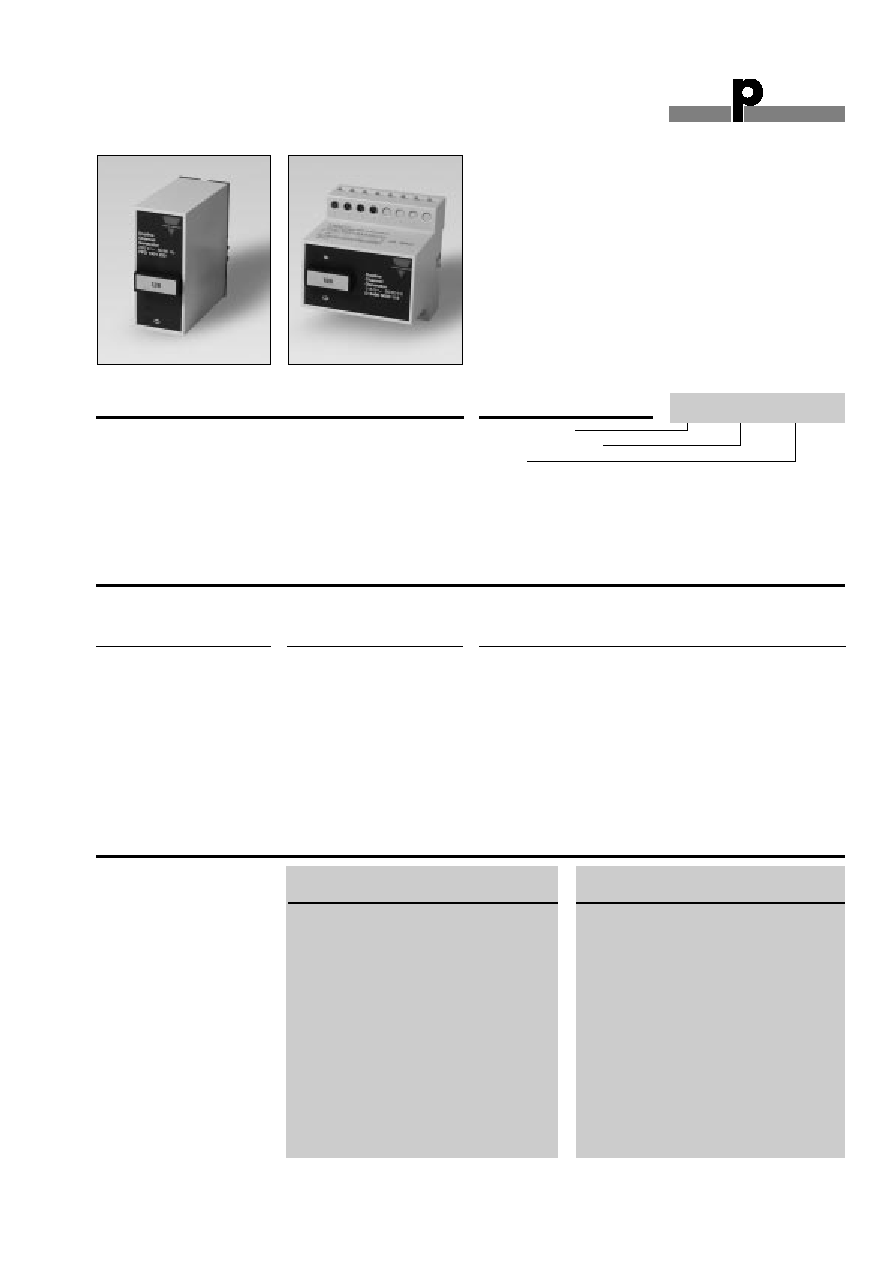
FPD 1901: standard channel
generator for all Dupline
Æ
sys-
tems. Number of channels
selectable by means of code
module.
D 3490 0000: Standard chan-
nel generator for all Dupline
Æ
Product Description
systems, especially suitable
for building installations. Iso-
lation according to IEC
60664/60664 A reinforced.
Increased Dupline
Æ
output
power for connection of non-
powered Dupline
Æ
transmitters.
Channel Generators
Types FPD 1901, D 3490 0000
Type Selection
Input/Output Specifications
FPD 1901 ...
D 3490 0000
(1, 2 or 3 sequences)
(1, 2 or 3 sequences)
Inputs
1 contact
1 contact
Function
Stop
Stop
Open loop voltage
12 VDC
12 VDC
Short-circuit current
5 mA
1.25 mA
Operating time for signal "1"
1 s
1 s
Operating time for signal "0"
10 ms
10 ms
Contact resistance
100 W
100 W
Cable length
3m
3 m
Insulation voltage
Input - Dupline
Æ
None
None
Outputs
Dupline
Æ
carrier
Dupline
Æ
carrier
Number of outputs
1
1
Output voltage
8.2 VDC
8.2 VDC
Current
40 mA
70 mA
Short-circuit protection
600 s
60 s
Type: Dupline
Æ
Channel generator
Supply
Ordering Key
FPD 1901 024
FPD
D 3490
Du line
Æ
Fieldbus
Installationbus
2
Specifications are subject to change without notice (28.09.99)
Dupline
Æ
is a registered trademark. A product of the CARLO GAVAZZI Group
FPD 1901, D 3490 0000
Input/Output Specifications (cont.)
FPD 1901 ...
D 3490 0000
(1, 2 or 3 sequences)
(1, 2 or 3 sequences)
Output (cont.)
Output impedance
-
25
Sequence time
Time for 1 pulse train (± 1%):
Time for 1 pulse train (± 1%)
Code module FMK 8
15.63 ms *
15.63 ms *
Code module FMK 16
23.44 ms *
23.44 ms *
Code module FMK 32
39.06 ms *
39.06 ms *
Code module FMK 64
70.31 ms *
70.31 ms *
Code module FMK 128
132.80 ms *
132.80 ms *
Distance to transmitters
100% (refer to "Cable Selection")
100% (refer to "Cable Selection")
* When using 2 or 3 sequences, the sequence time will be 2 or 3 times higher.
Supply Specifications
General Specifications
Power supply AC types
Overvoltage cat. III (IEC 60664)
Rated operational voltage
through pins A1 & A2
220 230 VAC +6%, -15% (IEC 60038)
120 120 VAC ± 10% (IEC 60038)
024 24 VAC ± 10%
through term. 21 & 22
230 230 VAC ± 15% (IEC 60038)
115 115 VAC ± 15% (IEC 60038)
024 24 VAC ± 15%
Frequency
45 to 65 Hz
Voltage interruption
40 ms
Rated operational power
Typ. 2.5 VA
Rated impulse withstand
voltage
220 4 kV
120 2.5 kV
024 800 V
Dielectric voltage
Supply - Dupline
Æ
FPD 1901 None
D 3490 0000
4 kVAC (rms)
Supply - Inputs
FPD 1901
2 kVAC (rms)
D 3490 0000
4 kVAC (rms)
Power supply DC types
Overvoltage cat. III (IEC 600664)
Rated operational voltage
through pins A1 & A2
824 15 to 30 VDC (ripple included)
Ripple
3 V
Reverse polarity protection
Yes
Current consumption
90 mA
Inrush current
1 A
Rated impulse withstand
voltage
800 V
Dielectric voltage
Supply - Dupline
Æ
None
Supply - Input
200 VAC (rms)
Power ON delay
1 s
Indication for
Supply ON
LED, green
Dupline
Æ
carrier*
LED, yellow
Environment
Degree of protection
IP 20
Pollution degree
3 (IEC 60664)
Operating temperature
-20∞ to +50∞C (-4∞ to +122∞F)
Storage temperature
-50∞ to +85∞C (-58∞ to +185∞F)
Humidity (non-condensing)
20 to 80%
Mechanical resistance
Shock
15 G (11 ms)
Vibration
2 G (6 to 55 Hz)
Dimensions
Material
(see "Technical Information")
D-housing, H4-housing
Weight
FPD 1901
AC type 200 g
DC type 125 g
D 3490 0000
250 g
Approvals
CSA, UL (only FPD 1901)
Mode of Operation
The channel generators gen-
erate pulse trains and syn-
chronize the transmission
signals for an entire system
of Dupline
Æ
modules. At the
same time they supply non-
powered Dupline
Æ
transmit-
ters. If the stop-function is
activated (pins 2 & 3 inter-
connected), the signal trans-
mission stops immediately,
and 8 VDC is supplied to the
two wires keeping all con-
nected Dupline
Æ
modules
ready for operation. When
the stop-function is deacti-
vated, a delay of approx. 2 s
elapses before the signal
transmission is resumed.
The stop input must be acti-
vated whenever new Dupli-
ne
Æ
modules are to be con-
nected to the system or
whenever Dupline
Æ
modules
need to be removed or
replaced.
The selection of 2 or 3 se-
quences means that 2 or 3
consecutive signals of a
transmitter must show iden-
tical status until the channel
generator changes the duty
cycle for the respective
channel. This change of
duty cycle causes the recei-
vers to change their status.
* Not applicable to FPD 1901
Du line
Æ
Fieldbus
Installationbus
Specifications are subject to change without notice (28.09.99)
3
Dupline
Æ
is a registered trademark. A product of the CARLO GAVAZZI Group
FPD 1901, D 3490 0000
Noise
suppression
Stop
+ -
DC
Power Supply
Noise
suppression
Stop
Power supply
~ ~
(+) (-)
Mode of Operation (cont.)
Note:
- Do not use 2 or 3 sequen-
ces if analog modules or
counters are connected to
the system.
- Do not use 3 sequences if
the modem interface D9091
... is used in the system.
- The transmission distance
of a Dupline
Æ
network is
reduced by 33% when
using 2 or 3 sequences, com-
pared to the figures given
under "Cable Selection".
In Dupline
Æ
systems with digi-
tal transmitters and receivers
the use of 2 or 3 sequences is
only recommended in cases
of extremely long cabling in
high noise level environment.
Application of 2 or 3 se-
quences results in absolutely
correct transmission but also
in a slow reaction time for the
system.
HF disturbance that is indu-
ced to the Dupline
Æ
may be
suppressed by interconnec-
tion of pins 4 & 6 (FPD 1901)
or terminals 4 & 1 (D 3490
0000. For inductive cables a
separate capacitor of less
than 1 µF may be mounted
between pins 3 & 6 (FPD
1901) or terminals 1 & 2 (D
3490 0000). But in the majori-
ty of cases the cable appears
to be capacitive requiring no
additional capacitor.
Note: It is highly recommend-
ed to place the channel ge-
nerator in the middle of a
Dupline
Æ
system.
Operation Diagram
Stop function
Power supply
Dupline
Æ
carrier
Accessories
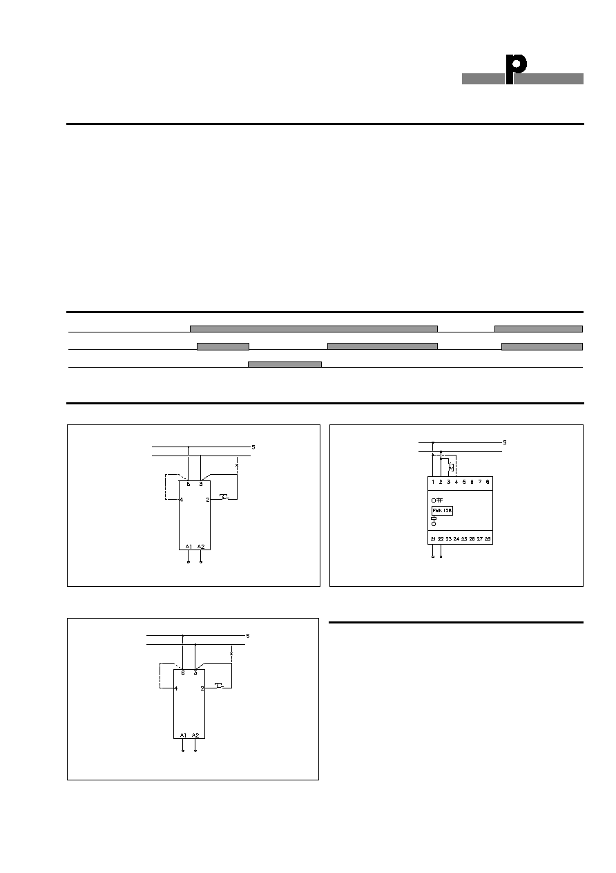
Wiring Diagrams
FPD 1901 AC supply
Noise
suppression
Stop
AC
Power Supply
D 3490 0000
FPD 1901 824 DC supply
Socket
D 411
Socket cover
BB 5
Hold down spring
HF
Front mounting bezel
FRS 2
DIN-rail for D 411
FMD 411
For further information refer to "Accessories".
S: signal wire
S: signal wire
S: signal wire