Specifications are subject to change without notice (18.09.06)
1
Monitoring Relays
Product Description
Ordering Key
Housing
Function
Type
Item number
Output
Power supply
Measuring range
∑ TRMS AC/DC over or under current
monitoring relay
∑ Current measuring through internal shunt
∑ Selection of measuring range by DIP-switches
∑ Measuring ranges from 0.1 mA to 10 A AC/DC
∑ Adjustable current on relative scale
∑ Adjustable hysteresis on relative scale
∑ Adjustable delay function (0.1 to 30 s)
∑ Programmable latching or inhibit at set level
∑ Output: 8 A SPDT relay N.D. or N.E. selectable
∑ For mounting on DIN-rail in accordance with
DIN/EN 50 022 (DIB01) or plug-in module (PIB01)
∑ 22.5 mm Euronorm housing (DIB01)
or 36 mm plug-in module (PIB01)
∑ LED indication for relay, alarm and power supply ON
∑ Galvanically separated power supply
Input (current level)
DIB01
Terminals Y1, Y2
PIB01
Terminals 5, 7
Measuring ranges
Direct
Internal resist.
Max. curr.
Selectable by DIP-switch
..5MA: 0.1 to 1 mA AC/DC
50
50 mA
0.2 to 2 mA AC/DC
50
50 mA
0.5 to 5 mA AC/DC
50
50 mA
Max. current for 1 s
100 mA
..50MA: 1 to 10 mA AC/DC
5
150 mA
2 to 20 mA AC/DC
5
150 mA
5 to 50 mA AC/DC
5
150 mA
Max. current for 1 s
500 mA
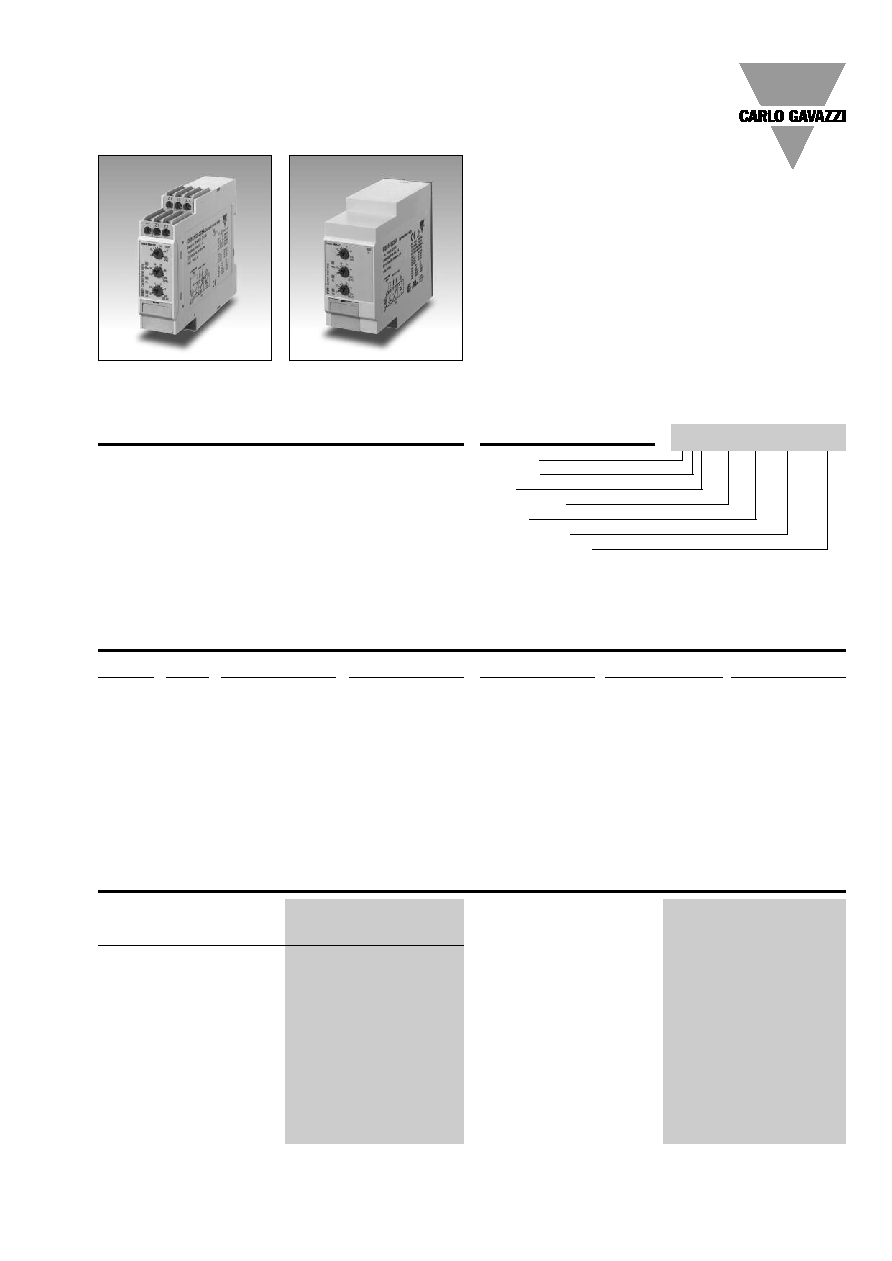
1-Phase True RMS AC/DC Over or Under Current
Types DIB01, PIB01
Input Specifications
DIB 01 C B23 5A
DIB01 and PIB01 are precise
TRMS AC/DC over or under
current (selectable by DIP-
switch) monitoring relays.
Direct measuring or through
current transformer.
Owing to the built-in latch
function, the ON-position of
the relay output can be
maintained. Inhibit function
can be used to avoid relay
operation when not desired
(maintenance, transitions).
The LED's indicate the state
of the alarm and the output
relay. Through the built-in
shunt it is possible to moni-
tor loads up to 10 A AC/DC.
DIB01
PIB01
Measuring ranges (cont.)
Internal resist.
Max. curr.
..500MA:10 to 100 mA AC/DC
0.5
700 mA
20 to 200 mA AC/DC
0.5
700 mA
50 to 500 mA AC/DC
0.5
700 mA
Max. current for 1 s
1.4 A
..5A:
0.1 to 1 A AC/DC
0.05
6 A
0.2 to 2 A AC/DC
0.05
6 A
0.5 to 5 A AC/DC
0.05
6 A
Max. current for 1 s
15 A
..10A:
1 to 10 A AC/DC
3 m
11 A
Max. current for 1 s
15 A
Type Selection
Mounting
Output
Measuring range
Supply: 24 VDC
Supply: 48 VDC
Supply: 24/48 VAC
Supply: 115/230 VAC
DIN-rail
SPDT
0.1 to 5 mA AC/DC
DIB 01 C 724 5mA
DIB 01 C 748 5mA
DIB 01 C B48 5mA
DIB 01 C B23 5mA
1 to 50 mA AC/DC
DIB 01 C 724 50mA
DIB 01 C 748 50mA
DIB 01 C B48 50mA
DIB 01 C B23 50mA
10 to 500 mA AC/DC
DIB 01 C 724 500mA
DIB 01 C 748 500mA
DIB 01 C B48 500mA
DIB 01 C B23 500mA
0.1 to 5 A AC/DC
DIB 01 C 724 5A
DIB 01 C 748 5A
DIB 01 C B48 5A
DIB 01 C B23 5A
1 to 10 A AC/DC
DIB 01 C 724 10A
DIB 01 C 748 10A
DIB 01 C B48 10A
DIB 01 C B23 10A
Plug-in
SPDT
0.1 to 5 mA AC/DC
PIB 01 C 724 5mA
PIB 01 C 748 5mA
PIB 01 C B48 5mA
PIB 01 C B23 5mA
1 to 50 mA AC/DC
PIB 01 C 724 50mA
PIB 01 C 748 50mA
PIB 01 C B48 50mA
PIB 01 C B23 50mA
10 to 500 mA AC/DC
PIB 01 C 724 500mA
PIB 01 C 748 500mA
PIB 01 C B48 500mA
PIB 01 C B23 500mA
0.1 to 5 A AC/DC
PIB 01 C 724 5A
PIB 01 C 748 5A
PIB 01 C B48 5A
PIB 01 C B23 5A
1 to 10 A AC/DC
PIB 01 C 724 10A
PIB 01 C 748 10A
PIB 01 C B48 10A
PIB 01 C B23 10A
2
Specifications are subject to change without notice (18.09.06)
DIB01, PIB01
Power supply
Overvoltage cat. III
Rated operational voltage
(IEC 60664, IEC 60038)
through terminals:
A1, A2 or A3, A2 (DIB01)
2, 10 or 11, 10 (PIB01)
724:
24 VDC ± 20%, insulated
784:
48 VDC ± 20%, insulated
B48:
24/48 VAC ± 15%
45 to 65 Hz, insulated
B23:
115/230 VAC ± 15%
45 to 65 Hz, insulated
Dielectric voltage
DC supply
AC supply
Supply to input
2 kV
4 kV
Supply to output
4 kV
4 kV
Input to output
4 kV
4 kV
Rated operational power
AC
4 VA
DC
3 W
Supply Specifications
Power ON delay
1 s ± 0.5 s or 6 s ± 0.5 s
Reaction time
(input signal variation from
-20% to +20% or from
+20% to -20% of set value)
Alarm ON delay
< 100 ms
Alarm OFF delay
< 100 ms
Accuracy
(15 min warm-up time)
Temperature drift
± 1000 ppm/∞C
Delay ON alarm
± 10% on set value ± 50 ms
Repeatability
± 0.5% on full-scale
Indication for
Power supply ON
LED, green
Alarm ON
LED, red (flashing 2 Hz
during delay time)
Output relay ON
LED, yellow
Environment
(EN 60529)
Degree of protection
IP 20
Pollution degree
3 (DIB01), 2 (PIB01)
Operating temperature
-20 to 60∞C, R.H. < 95%
Storage temperature
-30 to 80∞C, R.H. < 95%
Housing
Dimensions
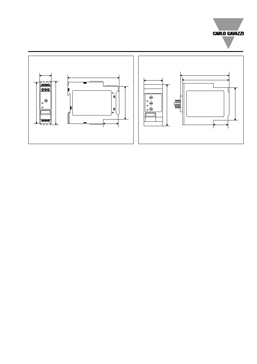
DIB01
22.5 x 80 x 99.5 mm
PIB01
36 x 80 x 94 mm
Weight
Approx. 150 g
Screw terminals
Tightening torque
Max. 0.5 Nm
acc. to IEC 60947
Approvals
UL, CSA (except 748)
CE Marking
Yes
EMC
Electromagnetic Compatibillity
Immunity
According to EN 61000-6-2
Emission
According to EN 61000-6-3
General Specifications
Output
SPDT relay
Rated insulation voltage
250 VAC
Contact ratings (AgSnO
2
)
µ
Resistive loads
AC 1
8 A @ 250 VAC
DC 12
5 A @ 24 VDC
Small inductive loads AC 15
2.5 A @ 250 VAC
DC 13
2.5 A @ 24 VDC
Mechanical life
30 x 10
6
operations
Electrical life
10
5
operations
(at 8 A, 250 V, cos
= 1)
Operating frequency
7200 operations/h
Dielectric strength
Dielectric voltage
2 kVAC (rms)
Rated impulse withstand volt. 4 kV (1.2/50 µs)
Output Specifications
Measuring ranges (cont.)
Standard CT (examples)
AAC
rms
Max. curr.
TADK2
50 A/5 A
5 to 50 A
60 A
TAD2
150 A/5 A
15 to 150 A
180 A
TAD6
400 A/5 A
40 to 400 A
480 A
TAD12
1000 A/5 A
100 to 1000 A
1200 A
TACO200
6000 A/5 A
600 to 6000 A
7200 A
Note:
The input voltage cannot
raise over 300 VAC/DC with
respect to ground (PIB01 only)
Contact input
DIB01
Terminals Z1, Y1
PIB01
Terminals 8, 9
Disabled
> 10 k
Enabled
< 500
Latch disable
> 500 ms
Input Specifications (cont.)

Specifications are subject to change without notice (18.09.06)
3
Adjust the input range set-
ting the DIP switches 1 and
2 as shown below (except
for models DIB01xxx10A
and PIB01xxx10A).
Select the desired function
setting the DIP switches 3 to
6 (1 to 4 for DIB01xxx10A
and PIB01xxx10A) as shown
below.
To access the DIP switches
open the grey plastic cover
as shown below.
Selection of level and time
delay:
Upper knob:
Setting of hysteresis on rela-
tive scale: 0 to 30% on set
value.
Centre knob:
Current level setting on rela-
tive scale: 10 to 110% on
full scale.
Lower knob:
Setting of delay on alarm
time on absolute scale (0.1
to 30 s).
DIB01, PIB01
Function/Range/Level and Time Delay Setting
Mode of Operation
DIB01 and PIB01 monitor
both AC and DC over or
under current through an
internal shunt.
Example 1
(connection between termi-
nals Z1, Y1 or 8, 9 - latching
function enabled)
The relay operates and latch-
es
in operating position
when the measured value
exceeds (or drops below) the
set level for more than the
set delay time. Provided that
the current has dropped
below (or has exceeded) the
set point (see hysteresis set-
ting), the relay releases when
the interconnection between
terminals Z1, Y1 or 8, 9 is
interrupted or the power
supply is interrupted as well.
The red LED flashes until the
delay time has expired or the
measured value comes back
to a non-alarm value (see
hysteresis setting).
Example 2 (Stardard CT)
(no connection between ter-
minals Z1, Y1 or 8, 9 - latch
function disabled)
The relay operates when the
measured value exceeds (or
drops below) the set level for
more than the set delay time.
It releases when the current
drops below (or exceeds) the
set level (see hysteresis set-
ting) or when power supply
is interrupted.
Note
When the inhibit contact is
opened, if the input signal is
already in alarm position, the
delay time needs to elapse
before relay activation.
10 A Models
Other Models
Relay working mode
ON: Normally De-energized
OFF: Normally Energized
Power ON delay
ON: 6 s ± 0.5 s
OFF: 1 s ± 0.5 s
Contact input
ON: Latch function enable
OFF: Inhibit function enable
Monitoring function
ON: Over current
OFF: Under current
Relay working mode
ON: Normally De-energized
OFF: Normally Energized
Measuring range
SW1
ON
ON
OFF
SW2
OFF
ON
ON
5MA
1 mA
2 mA
5 mA
50MA
10 mA
20 mA
50 mA
500MA 100 mA 200 mA 500 mA
5A
1 A
2 A
5 A
Power ON delay
ON: 6 s ± 0.5 s
OFF: 1 s ± 0.5 s
Contact input
ON: Latch function enable
OFF: Inhibit function enable
Monitoring function
ON: Over current
OFF: Under current

4
Specifications are subject to change without notice (18.09.06)
Operation Diagrams
Wiring Diagrams
DIB01, PIB01
Over current - N.D. relay
Under current - N.D. relay
Under current - Latch function - N.D. relay
Over current - Inhibit function - N.D. relay
Example 1
N (-)
PE
m
Z1
Y1
Y2
A1
A3
A2
15
16
18
L
Latch/Inhibit
Contact
Example 2
N (-)
m
Z1
Y1
Y2
A1
A3
A2
15
16
18
L
I
I
24/48 VDC (+)
48/230 VAC 24/115 VAC
24/48 VDC (+)
48/230 VAC 24/115 VAC
DIB01
Example 1
N (-)
PE
m
8
9
5
7
10
1
4
3
L
Latch/Inhibit
Contact
Example 2
N (-)
m
8
9
5
7
10
1
4
3
L
11
2
I
I
24/48 VDC (+)
48/230 VAC 24/115 VAC
24/48 VDC (+)
48/230 VAC 24/115 VAC
PIB01
Specifications are subject to change without notice (18.09.06)
5
36
8
0
94
28.5
6
3
90
22.5
8
0
8
3
.
5
99.5
6
3
28.5
Dimensions
DIN-rail
Plug-in
DIB01, PIB01