Specifications are subject to change without notice (01.09.06)
1
Monitoring Relays
Product Description
Ordering Key
Housing
Function
Type
Item number
Output
Power supply
Number of pumps
∑ Pump alternating relay for 2 or 3 pumps
∑ Output: 2 x 5 A SPST relay or 3 x 5 A SPST
∑ For mounting on DIN-rail in accordance with
DIN/EN 50 022
∑ 35.5 mm DIN-rail housing
∑ LED indication for relay and power supply ON
∑ Galvanically separated power supply
∑ Built-in delay for the second or third pump in case of
simultaneous activation is required
∑ Built-in function for automatic rotation of the pumps
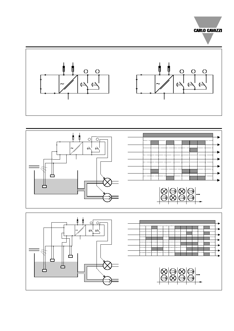
Contact input
Terminals
DLA71...2P (normal mode)
ON/OFF 1 pump
C, S1
ON/OFF 2 pumps
C, S2
DLA71...2P (differential mode)
first pump starts
C, S1
first pump stops
C, S3
second pump start
C, S2
second pump stop
C, S4
DLA71...3P (normal mode)
ON/OFF 1 pump
C, S1
ON/OFF 2 pumps
C, S2
ON/OFF 3 pumps
C, S3
DLA71...3P (full mode)
ON 1 pump
C, S1
ON 2 pumps
C, S2
ON 3 pumps
C, S3
OFF all pumps
C, S4
Disabled
> 10 k
Enabled
< 1 k
Voltage
< 25 V
Current
< 2 mA
Pump alternating
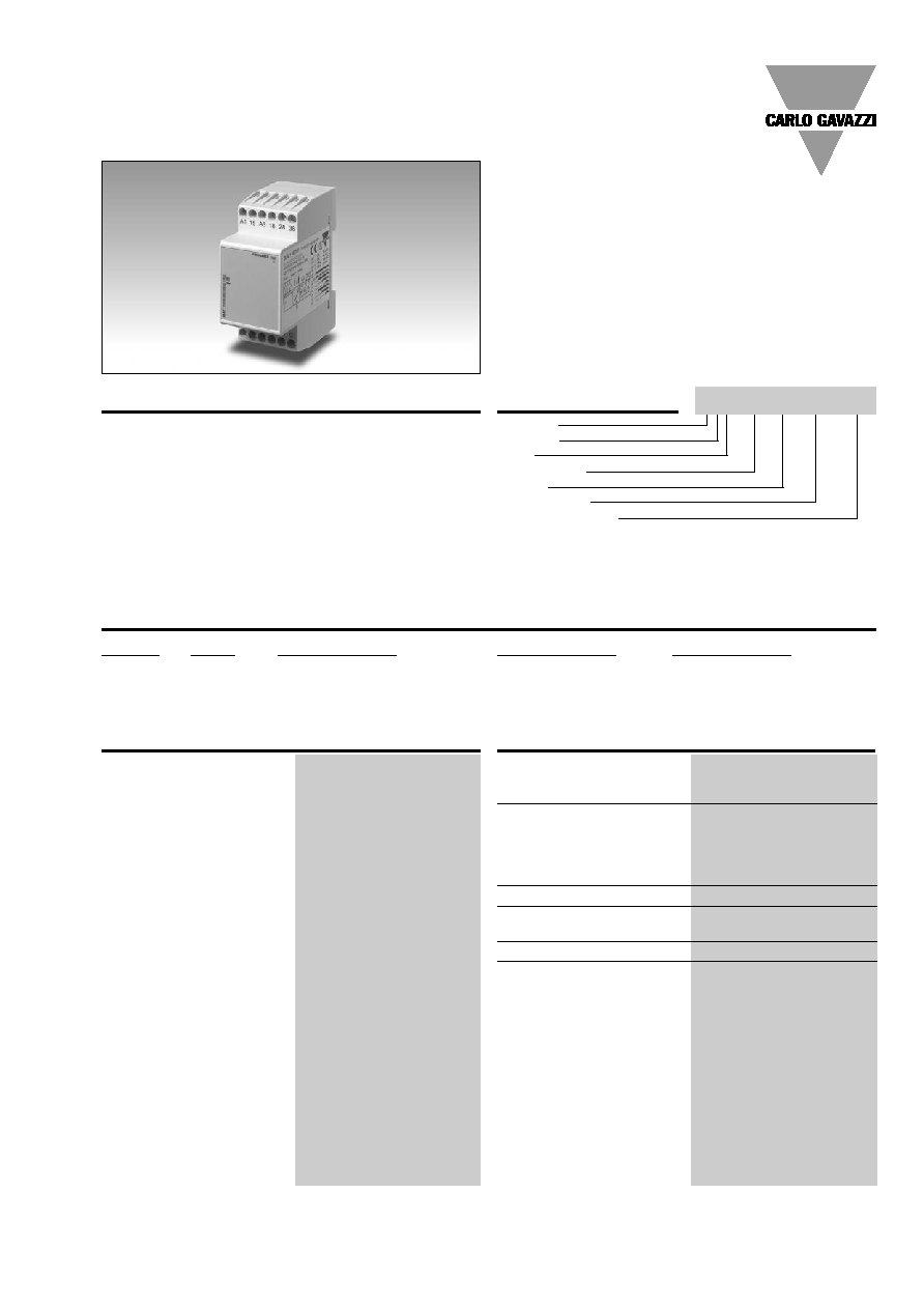
Type DLA71
Input Specifications
DLA 71 T B23 3P
DLA71 is relay made to
alternate 2 or 3 pumps in a
multiple pump system. In
case of need (i.e.: overflow)
the second, or even the third
pump can be activated
together with the first one.
In case more than one pump
is required to start at the
same time, the pumps start
10 s after the previous to
avoid big inrush current.
The LED indicates the state
of the alarm and the output
relay.
35.5 mm wide housing suit-
able both for back and front
panel mounting.
Type Selection
Mounting
Output
Function
Supply: 24/48 VAC
Supply: 115/230 VAC
DIN-rail
2 x SPST
For two pumps
DLA 71 D B48 2P
DLA 71 D B23 2P
DIN-rail
3 x SPST
For three pumps
DLA 71 T B48 3P
DLA 71 T B23 3P
Output
DLA71...2P
2 x SPST NO relay
DLA71...3P
3 x SPST NO relay
Rated insulation voltage
250 VAC
Contact ratings (AgSnO
2
)
µ
Resistive loads
AC 1
5 A @ 250 VAC
DC 12
5 A @ 24 VDC
Small inductive loads AC 15
1.5 A @ 250 VAC
DC 13
1.5 A @ 24 VDC
Mechanical life
30 x 10
6
operations
Electrical life
10
5
operations
(at 5 A, 250 V, cos
= 1)
Operating frequency
7200 operations/h
Dielectric strength
Dielectric voltage
2 kVAC (rms)
Rated impulse withstand volt. 4 kV (1.2/50 µs)
Output Specifications

2
Specifications are subject to change without notice (01.09.06)
Mode of Operation
DLA71 is made for pumping
systems where 2 or 3 pumps
are in parallel. It lets the
pumps work alternatively,
allowing more
pumps to
work togheter in case of
need.
Example 1
(emptying a basin, 2-pump
system)
As soon as the liquid reach-
es switch S1 one pump
starts. As soon as S1
switches back the pump
stops. When switch S1 is
activated again the other
pump starts allowing uni-
form wear and tear of all the
pumps. If switch S2 is acti-
vated both pumps start (2
pumps running at the same
time). When S2 switches
back the pump running
since most time stops.
Example 2
(emptying a basin, 2-pump
system, differential mode)
In this case the pumps are
separately started and
stopped by the two pairs of
switches S1, S2 and S3, S4.
Appropriate positioning
allows the pumps to work
together in case of need.
Note (2-pump system)
If the system is continuously
working with only one pump,
after working for 6 hours,
DLA71 stops the pump and
the second one automatical-
ly starts.
This rotation is repeated
every 6 hours of single and
continuative work of a
pump.
Example 3
(emptying a basin, 3-pump
system, normal mode)
The system works exactly as
described in example 1
except that if switch S3 is
reached three pumps work
at the same time. When they
switch back the pumps are
turned off in sequence start-
ing from the one running
longer.
Example 4
(emptying a basin, 3-pump
system, full mode)
As soon as the liquid reach-
es switch S1 one pump
starts. When it drops below
switch S4 it stops. If switch
S1 is triggered again another
pump starts. If switch S2 is
activated a second pump
starts (rescue function). If
switch S3 is activated all the
pumps operate. The only
switch to stop all the pumps
active at a certain time is S4.
Note (3-pump system)
If the system is continuously
working with only one pump,
after working for 6 hours,
DLA71 stops the pump and
the second one automatical-
ly starts. If also the second
pump works continuously
alone for 6 hours, it is
stopped and the third pump
is then started.
If a couple of pumps is con-
tinuously working for 6
hours, the one running for
more time stops and the free
one starts.
This rotation is repeated
every 6 hours of continuative
work of a pump or a couple
of pumps.
Note (2 and 3-pump sys-
tems)
In case the task is to fill a
basin, all the switches are
reversed in the basin itself.
DLA71
Indication for
Power supply ON
LED, green, steady
One Pump ON
as above, flashing 1 Hz
Two Pumps ON
as above, flashing 2 Hz
Three Pumps ON(DLA71...3P) as above, flashing 3 Hz
Note: if more than one pump
is active, the indication refers
to the pump started last.
Environment
(EN 60529)
Degree of protection
IP 20
Pollution degree
3
Operating temperature
-20 to 60∞C, R.H. < 95%
Storage temperature
-30 to 80∞C, R.H. < 95%
Housing
Dimensions
35.5 x 81 x 67.2 mm
Material
PA 66
Weight
Approx. 135 g
Screw terminals
Tightening torque
Max. 0.5 Nm
acc. to IEC 60947
Approvals
UL, CSA
CE Marking
Yes
EMC
Electromagnetic Compatibillity
Immunity
According to EN 61000-6-2
Emission
According to EN 61000-6-3
General Specifications
Power supply
Overvoltage cat. III
Rated operational voltage
(IEC 60664, IEC 60038)
through terminals:
A1, A2 or A3, A2
B48:
24/48 VAC ± 15%
45 to 65 Hz, insulated
B23:
115/230 VAC ± 15%
45 to 65 Hz, insulated
Dielectric voltage
Supply to input
4 kV (1.2/50 µs)
Supply to output
4 kV (1.2/50 µs)
Input to output
4 kV (1.2/50 µs)
Rated operational power
AC
3 VA
Supply Specifications
Reaction time
Closing input
< 100 ms
Opening input
< 100 ms
Minimum delay to activate
the rescue pumps
10 s
Continous working time to
activate the rotation pumps
6 h ± 10%
General Specifications