 | –≠–ª–µ–∫—Ç—Ä–æ–Ω–Ω—ã–π –∫–æ–º–ø–æ–Ω–µ–Ω—Ç: DMC01CB23 | –°–∫–∞—á–∞—Ç—å:  PDF PDF  ZIP ZIP |

Specifications are subject to change without notice (21.11.05)
1
Timers
Multifunction
Types DMC01, PMC01
∑ Time range 0.1 s to 100 h
∑ 7 knob selectable functions
Op - Delay on operate, manual start
Oa - Delay on operate, automatic and manual start
In - Interval, manual start
Ia - Interval, automatic and manual start
Nr - Interval with no time reset, manual start
Na - Interval with no time reset, automatic and
manual start
Dr - Delay on release
∑ Knob selection of time range
∑ Knob adjustable time setting
∑ External adjustable time setting available
∑ Repeatability:
0.2%
∑ DC supply for PNP/NPN and Namur sensors
∑ Output: 8 A SPDT or 2 x 8 A SPDT relay
∑ For mounting on DIN-rail in accordance with DIN/EN
50 022 or Plug-in
∑ 22.5 mm or 45 mm Euronorm or 36 mm Plug-in
module housing
∑ LED indication for relay status and power supply ON
Product Description
Multi-voltage timer with 7
knob selectable functions
and 7 knob selectable time
ranges within 0.1s and
100h. Remote time setting
available.
15 VDC, 10 mA (1 relay) or 24
VDC, 15 mA (2 relays) supply
for PNP/NPN sensors and 8.2
VDC supply for Namur sensor.
For mounting on DIN-rail
(DMC01) or Plug-in (PMC01).
Type Selection
Mounting
Output
Housing
Supply: 24 VDC
Supply: 24 or 48 VAC
Supply: 115 or 230 VAC
For DIN-rail
1 x SPDT
D - 22.5 mm
DMC 01 C 724
DMC 01 C B48
DMC 01 C B23
For DIN-rail
2 x SPDT
D - 45 mm
DMC 01 D 724
DMC 01 D B48
DMC 01 D B23
Mounting
Output
Housing
Supply: 24 VDC
Supply: 24 VAC
Supply: 115 VAC
Supply: 230 VAC
Plug-in
1 x SPDT
P - Housing
PMC 01 C 724
PMC 01 C 024
PMC 01 C 115
PMC 01 C 230
Plug-in
2 x SPDT
P - Housing
PMC 01 D 724
PMC 01 D 024
PMC 01 D 115
PMC 01 D 230
Time Specifications
Time ranges
Knob selectable
0.1 to 1 s
1
to 10 s
6
to 60 s
60 to 600 s
0.1 to 1 h
1
to 10 h
10 to 100 h
Setting accuracy
5%
Repeatability
0.2%
Time variation
Within rated power supply
0.05%/V
Within ambient temperature
0.2%/∞C
External time setting
Linear remote potentiometer
10 k
Max length of pot. cable
3 m
Reset
Manual reset of time
and/or relay
Close the trigger contact
Pulse duration
10 ms
Power supply interruption
1 relay versions:
700 ms
2 relays versions:
200 ms
PNP/NPN sensor supply output
1 relay versions:
15 VDC, 10 mA
2 relays versions:
24 VDC, 15 mA
pins + and - or 6 and 7
pin + or 6 positive
Namur sensor connection
8.2 VDC, 1k
pins + and S or 6 and 5
pin + or 6 positive
DMC01C
DMC01D
PMC01
Ordering key
DMC 01 C B23
Housing
Function
Type
Item number
Output
Power Supply

2
Specifications are subject to change without notice (21.11.05)
DMC01, PMC01
Supply Specifications
General Specifications
Power supply
Overvoltage cat. III
Rated operational voltage
(IEC 60664, IEC 60038)
through terminals:
A1, A2 or A1, A3 (DMC01)
B48
24 or 48 VAC ± 15%
45 to 65 Hz
B23
115 or 230 VAC ± 15%
45 to 65 Hz
724
24 VDC ± 20%
2, 10 (PMC01)
024
24 VAC ± 15%,45 to 65 Hz
115
115 VAC ± 15%,45 to 65 Hz
230
230 VAC ± 15%,45 to 65 Hz
724
24 VDC ± 20%
Voltage interruption
10 ms
Rated operational power
AC supply:
5 VA
DC supply:
2 W
Power ON delay
100 ms
Reaction time from trigger
Delayed contact(s)
< 10 ms
Instantaneous contcat
< 20 ms
Indication for
Power supply ON
LED, green
Output relays ON
LED, yellow (flashing when
timing)
Environment
(EN 60529)
Degree of protection
IP 20
Pollution degree
3 (DMC01), 2 (PMC01)
(IEC 60664)
Operating temperature
-20 to 60 ∞C, R.H. < 95%
Storage temperature
-30 to 80 ∞C, R.H. < 95%
Housing dimensions
DMC01C
22.5 x 80 x 99.5 mm
DMC01D
45 x 80 x 99.5 mm
PMC01
36 x 80 x 94 mm
Weight
120 to 260g depending on
model
Screw terminals
(DMC01)
Tightening torque
Max 0.5 Nm according to
IEC EN 60947
Approval
UL, CSA
CE Marking
Yes
EMC
Electromagnetic Compatibility
Immunity
According to EN 61000-6-2
Emission
According to EN 61000-6-3
Timer Specifications
According to EN 61812-1
Function/Range/Time Setting
Adjust the function setting
the DIP switches 1 to 6 as
shown below (1 to 4 for
DMC01Cxxx).
Note 1: DIP switch 5 must
be kept ON when using
PMC01Dxxx.
Note 2: DIP switch 6 does
not have any effect on the
PMC01Cxxx working mode.
To access the DIP switches
open the grey plastic cover
using a screwdriver as
shown below.
Upper knob:
Selection of function:
Op - Delay on operate,
manual start
Oa - Delay on operate,
automatic and manual
start
In - Interval, manual start
Ia - Interval, automatic
and manual start
Nr - Interval with no time
reset, manual start
Na - Interval with no time
reset, automatic and
manual start
Dr - Delay on release
Centre knob:
Time setting on relative
scale: 1 to 10 with respect
to the chosen range.
Lower knob:
Setting of time range
External potentiometer
(DMC01D, PMC01C):
Time setting on relative
scale: 1 to 10 with respect
to the chosen range.
Output Specifications
Output
1 or 2 x SPDT relay
Rated insulation voltage
250 VAC (RMS)
Contact Ratings (AgSnO
2
)
µ
Resistive loads
AC 1
8 A @ 250 VAC
DC 12
5 A @ 24 VDC
Small inductive loads AC 15
2.5 A @ 250 VAC
DC 13
2.5 A @ 24 VDC
Mechanical life
30 x 10
6
operations
Electrical life
10
5
operations
(at 8 A, 250 V, cos
= 1)
Operating frequency
< 7200 operations / h
Dielectric strength
Dielectric voltage
2 kVAC (RMS)
Rated impulse withstand volt. 4 kV (1.2/50 µs)
Sensor type selection
ON ON OFF OFF: PNP/NPN sensor,
Open collector
or contact
OFF OFF ON ON:
Namur sensor
Time setting (DMC01D and PMC01C)
ON:
Centre knob on front
OFF:
External trimmer
Second relay
ON:
Instantaneous
OFF:
DPDT
DMC01D,
PMC01C,
PMC01D
DMC01C

Specifications are subject to change without notice (21.11.05)
3
DMC01, PMC01
Mode of Operation
Function Op: Delay on
operate, manual start
The time period begins as
soon as the trigger contact
is closed.
At the end of the set delay
time the relay operates and
doesn't release until the trig-
ger contact is closed again
or the power supply is dis-
connected. When the trigger
contact is closed, the relay
releases and a new time
period starts.
Function Oa: Delay on
operate, automatic and
manual start
The time period begins as
soon as the power supply is
connected.
At the end of the set delay
time the relay operates and
doesn't release until the trig-
ger contact is closed or the
power supply is disconnect-
ed. When the trigger contact
is closed, the relay releases
and a new time period
starts.
Function In: Interval,
manual start
The relay operates and the
time period begins as soon
as the trigger contact is
closed. The relay releases at
the end of this period or
when the power supply is
disconnected. The relay
operates again when the
trigger contact is closed
again. If the trigger contact
is closed before the end of
the delay time, the relay
keeps ON and a new time
period starts.
Function Ia: Interval, auto-
matic and manual start
The relay operates and the
time period begins as soon
as the power supply is con-
nected.
The relay releases at the end
of this period or when the
power supply is disconnect-
ed. The relay operates again
when the trigger contact is
closed. If the trigger contact
is closed before the end of
the delay time, the relay
keeps ON and a new time
period starts.
Function Nr: Interval with
no time reset, manual start
The relay operates and the
time period begins as soon
as the trigger contact is
closed. The relay releases at
the end of this period or
when the power supply is
disconnected. The relay
operates again when the
trigger contact is closed
again.
Function Na: Interval with
no time reset, automatic
and manual start
The relay operates and the
time period begins as soon
as the power supply is con-
nected.
The relay releases at the end
of this period or when the
power supply is disconnect-
ed. The relay operates again
when the trigger contact is
closed.
Function Dr: Delay on
release
The relay operates as soon
as the trigger contact is
closed. The time period
begins when the trigger con-
tact is opened. The relay
releases at the end of the
set delay time or when the
power supply is disconnect-
ed. The relay operates again
when the input contact is
closed again. If it is closed
before the end of the delay
time the relay keeps ON, a
new time period begins as
soon as the contact is
opened again.
Example1: Delay on
operate with remote
control time setting:
Using the delay on operate
function, DMC01D or
PMC01C can be used to set
the working delay of an
equipment (i.e. a pump) by a
knob placed on a panel. It is
only necessary to connect
an external potentiometer to
the suitable pins (T1, T2, T3
for DMC01D or 8. 9. 11 for
PMC01C) and mount the
knob on the control panel.
Note:
The external potentiometer
must be connected before
the product operates. The
cable length must be below
3 m
Example 2: Interval with
NPN or Namur proximity
sensor.
Using the Interval function
and a NPN or Namur prox-
imity sensor, DMC01 and
PMC01 can be used to
monitor the actual presence
of an object (i.e. a can) in
the right place on a convejor
belt. In fact the sensor trig-
gers the timer each time it
detects an object on the
belt, so the relay keeps ON
as long as there is no gap
on the belt. As soon as there
is a gap on the belt, the
relay switches OFF and an
alarm can be activated.
Yellow LED working mode
Timing:
Slow blinking
Relay ON:
See operation diagrams
Incorrect knobs position:
Fast blinking
4
Specifications are subject to change without notice (21.11.05)
DMC01, PMC01
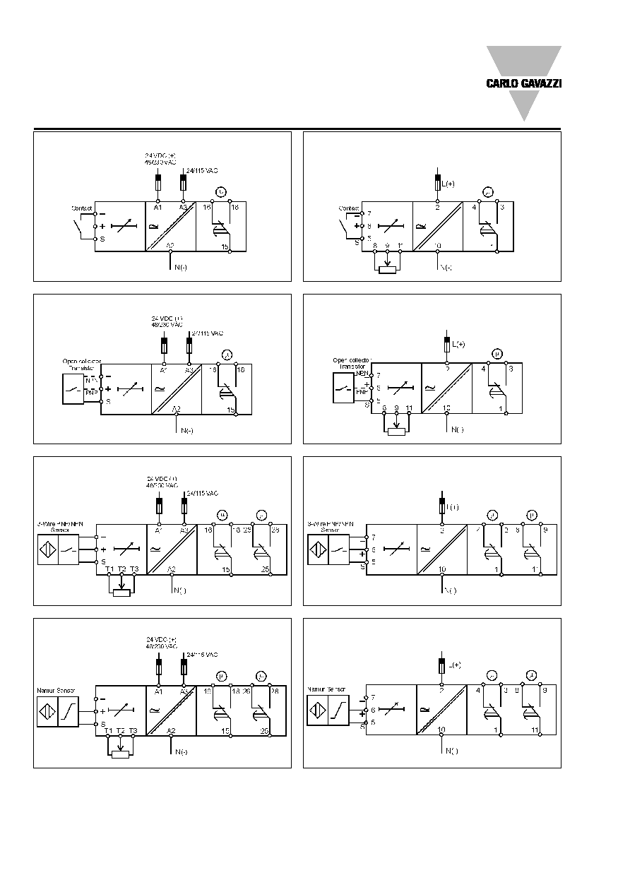
Wiring Diagrams
DMC01C - Contact input
PMC01C - Contact input
DMC01C - Open collector input
PMC01C - Open collector input
DMC01D - PNP / NPN sensor input
PMC01D - PNP / NPN sensor input
DMC01D - Namur sensor input
PMC01D - Namur sensor input
Specifications are subject to change without notice (21.11.05)
5
DMC01, PMC01
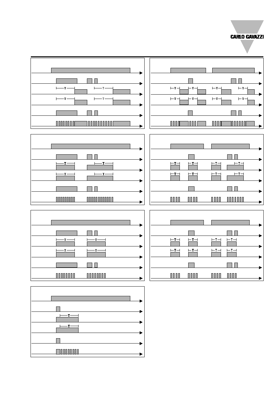
Operation Diagrams
Function Op - Delay on operate, manual start
Function Oa - Delay on operate, automatic and manual start
Function In - Interval, manual start
Function Ia - Interval, automatic and manual start
Function Nr - Interval with no time reset, manual start
Function Na - Interval with no time reset, automatic and manual start
Function Dr - Delay on release
Power supply
Trigger input
Relay 1 ON
LED
Relay 2 ON
(delayed)
Relay 2 ON
(instant.)
Power supply
Trigger input
Relay 1 ON
LED
Relay 2 ON
(delayed)
Relay 2 ON
(instant.)
Power supply
Trigger input
Relay 1 ON
LED
Relay 2 ON
(delayed)
Relay 2 ON
(instant.)
Power supply
Trigger input
Relay 1 ON
LED
Relay 2 ON
(delayed)
Relay 2 ON
(instant.)
Power supply
Trigger input
Relay 1 ON
LED
Relay 2 ON
(delayed)
Relay 2 ON
(instant.)
Power supply
Trigger input
Relay 1 ON
LED
Relay 2 ON
(delayed)
Relay 2 ON
(instant.)
Power supply
Trigger input
Relay 1 ON
LED
Relay 2 ON
(delayed)
Relay 2 ON
(instant.)
ON
OFF
ON
OFF
ON
OFF
ON
OFF
ON
OFF
ON
OFF
ON
OFF
ON
OFF
ON
OFF
ON
OFF
ON
OFF
ON
OFF
ON
OFF
ON
OFF
ON
OFF
ON
OFF
ON
OFF
ON
OFF
ON
OFF
ON
OFF
ON
OFF

6
Specifications are subject to change without notice (21.11.05)
DMC01, PMC01
Dimensions
22.5
80
83.5
99.5
63
28.5
45
80
83.5
99.5
63
28.5
DIN-rail
DIN-rail
36
80
94
28.5
63
90
Plug-in