Specifications are subject to change without notice (26.10.99)
1
True Delay on Release
∑ Time range 0.1 s to 10 h
∑ Knob-adjustable time setting
∑ Knob selection of time range
∑ Oscillator-controlled time circuit
∑ Output: 5 A SPDT
∑ For mounting on DIN-rail in accordance with
DIN/EN 50 022
∑ 22.5 mm Euronorm housing
∑ LED-indication for power supply ON
∑ AC and DC multi power supply
Product Description
Ordering Key
Housing
Function
Type
Output
Power supply
Time range
Mono-function timer with 3
selectable time ranges within
0.1 s to 1 m or 1 m to 10 h.
Built-in battery (NiCd) will be
charged while power supply
is applied. For mounting on
DIN-rail. Often used for moni-
toring an external power sup-
ply and signalling drop-out of
power supply after a preset
time delay.
Type Selection
Mounting
Output
Time range
Supply: 24 - 230 VAC/DC
For DIN-rail
SPDT
0.1 s - 1 m
EBB C M23 1M
SPDT
1 m - 10 h
EBB C M23 10H
Time Specifications
Time ranges
Type 1 M
Selectable by rotary switch
0.1 s - 1 s
1 s - 10 s
0.1 m - 1 m
Type 10 H
Selectable by rotary switch
1 m - 10 m
10 m - 100 m
1 h - 10 h
Time range accuracy
±5% on max.
min. actual time
min. set time
Time variation
Within rated battery voltage
1%
and ambient temperature
0.2%/∞C
Reset
Time
power supply applied
100 ms
Output Specifications
Output
SPDT relay
Rated insulation voltage
250 VAC (contact/elect.)
Contact ratings (AgCdO)
µ (micro gap)
Resistive loads
AC 1
5 A/250 VAC
DC 1
5 A/24 VDC
Small inductive loads
AC 15
2 A/250 VAC
DC 13
3 A/24 VDC
Mechanical life
10
7
operations
Electrical life
10
5
operations
(at max. load)
Operating frequency
7200 operations/h
Dielectric strength
Dielectric voltage
2 kVAC (rms)
Rated impulse withstand volt.
4 kV (1.2/50 µs)
Type EBB
Timers
EBB C M23 1M
2
Specifications are subject to change without notice (26.10.99)
EBB
General Specifications
EMC
Electromagnetic
Compatibility
Immunity
Acc. to IEC 60801-4
Acc. to IEC 60801-5
Power ON delay
200 ms
Indication for
Power supply ON
LED, green
Environment
Degree of protection
IP 20
Pollution degree
3
Operating temperature
0∞ to +45∞C (+10∞ to +113∞F)
Storage temperature
-40∞ to +50∞C (-40∞ to +122∞F)
Weight
135 g
Screw terminals
Tightening torque
Max. 0.5 Nm acc. to IEC 60947
Approvals
UL, CSA
Supply Specifications
Power supply
Overvoltage cat. III (IEC 60664)
Rated operational voltage
(IEC 60038)
through term. A1 & A2 M23
24-230 VAC/DC, ±15%
Frequency
50/60 Hz, -5/+5 Hz
Voltage interruption
40 ms
Dielectric voltage
None
Rated impulse withstand
voltage
4 kV (1.2/50 µs)
Rated operational power
3 VA
Built-in battery for
time function
Nominal voltage
4.8 V
Min./max. battery voltage
4.2 VDC/6.2 VDC
Charging current
2 mA
Discharging current
0.5 mA
Capacity
Approx. 60 mA/h
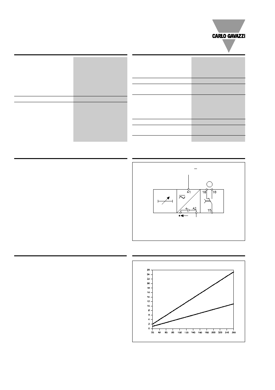
Wiring Diagram
µ
L
N
Battery
test:
min. 4.2 V
max. 6.2 V
Curves
Time Setting
Selection of time ranges
Upper knob:
3-position rotary switch.
Time setting
Lower knob:
Knob-adjustable on relative
scale 1-10.
The relay operates immedia-
tely after power supply is ap-
plied.
When power supply is inter-
rupted the time period starts
and at expiration of the set
time period the relay releases.
If power supply is reapplied
before the relay has released,
the time is reset and the relay
remains on.
The built-in battery (NiCd) will
be charged while power sup-
ply is applied.
Note:
The EBB should not be ope-
rated by short pulses. For this
purpose the relays EMB C T23,
operated by means of an ex-
ternal contact function, should
be used.
Battery test is performed on
terminals + and A2.
It is recommended to connect
the EBB to the power supply
for 42 h before it is put into re-
gular service in order to com-
pensate for energy losses due
to e.g. a long storage period.
Mode of Operation
24-230 V
~
Delay time between two power supply applications
Delay time (sec.)
Power supply
AC-Supply
DC-Supply
Specifications are subject to change without notice (26.10.99)
3
EBB
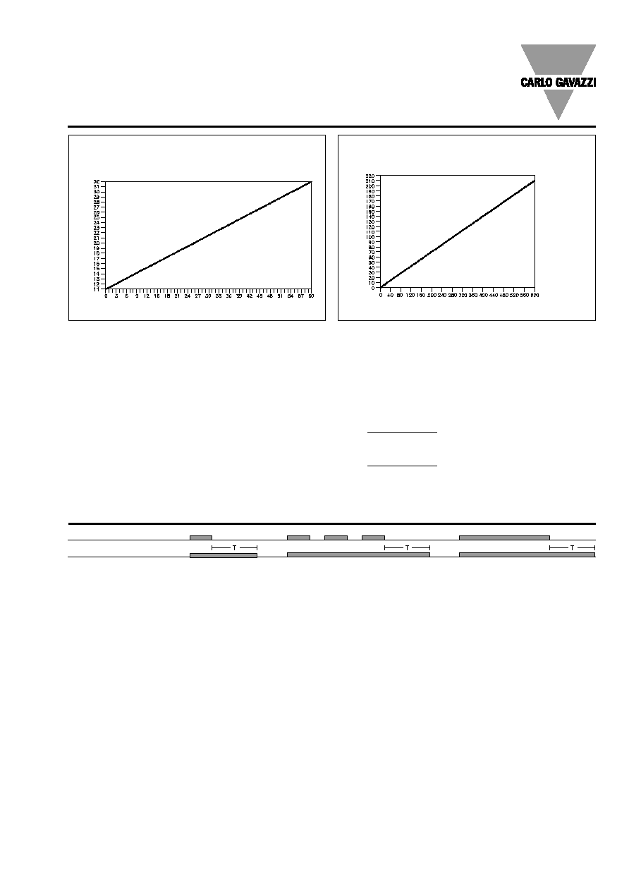
Curves (cont.)
Charging time for time ranges up to 60 sec.
Time range (sec.)
Time range (min.)
The above tables indicate the
charging time needed to keep
the built-in battery fully
charged for a certain adjusted
time period.
Example
Adjusted time period 60 s,
battery charging time will be
32 s.
At 5 operations: 5 x 60 s, bat-
tery charging time will be 5 x
32 s.
If the calculated charging time
cannot be obtained, then the
battery voltage has to be
checked, as it must not drop
below 4.2 VDC (min. battery
voltage).
Test can be performed on ter-
minals + and A2.
Battery consumption at the
expiration of each time pe-
riod.
Calculation of battery capac-
ity for individually adjusted
time ranges:
0.5 mA x T(sec)
0.5 mA x T(min)
1M:
10H:
3600
60
+ 0.0042 mAH = mAH
+ 0.0042 mAH = mAH
Operation Diagram
Power supply
Relay ON
Char
ging time (sec.)
Charging time for time ranges up to 600 min. (10 h)
Char
ging time (sec.)