Specifications are subject to change without notice
1
1-Phase AC/DC Over Current (Shunt)
Type EIK
Current and Voltage Controls
∑ AC/DC over current (open circuit)
metering relay
∑ Measuring through external shunt
∑ 3-position rotary switch for selection of measuring range
∑ Measuring ranges:
10-50 mV, 12-60 mV, 30-150 mV or
20 -100 mV, 24-120 mV, 60-300 mV
∑ Adjustable limit on relative scale
∑ Adjustable time function (0.1-10 s)
∑ Adjustable hysteresis
∑ Programmable latching at set level
∑ Output: 5 A SPDT
∑ For mounting on DIN-rail in accordance with
DIN/EN 50 022
∑ 22.5 mm Euronorm housing
∑ LED-indication for relay and power supply ON
∑ Galvanically separated power supply
Ordering Key
Housing
Function
Type
Output
Power supply
EIK C 230
Product Description
EIK is a precise AC/DC over
current (shunt) metering re-
lay. Measures the voltage of
an externally connected
standard shunt also for high
current applications. The built-
in LED's indicate the exact
status of the output relay. The
advantage of using the latch
function is that the output re-
lay can be kept energized so
e.g. a short-circuit can be
indicated.
Type Selection
Mounting
Output
Measuring range
Supply: 24 VAC
Supply: 115 VAC
Supply: 230 VAC
For DIN-rail
SPDT
10 - 300 mV
EIK C 024
EIK C 115
EIK C 230
Input Specifications
Input
Through terminals Y1 & Y2
range x 1
Through terminals Y1 & Y3
range x 2
Measuring ranges
Internal resist. Max. volt.
x 1 input:
Rotary
1: 10 - 50 mV
270
1 V
Switch
2: 12 - 60 mV
270
1 V
Position
3: 30 - 150 mV
270
1 V
x 2 input:
Rotary
1: 20 - 100 mV
540
2 V
Switch
2: 24 - 120 mV
540
2 V
Position
3: 60 - 300 mV
540
2 V
Max. line voltage
277/480 VAC/DC
Latching
Interconnection of
terminals Z1 & Z2.
Latching at set level
Output Specifications
Output
SPDT relay
Rated insulation voltage
250 VAC (contact/elect.)
Contact ratings (AgCdO)
µ (micro gap)
Resistive loads
AC 1
5 A, 250 VAC
DC 1
5 A, 24 VDC
Small inductive loads AC 15
2 A, 250 VAC
DC 13
3 A, 24 VDC
Mechanical life
40 x 10
6
operations
Electrical life
10
5
operations
(at max load)
Operating frequency
7200 operations/h
Dielectric strength
Dielectric voltage
2 kVAC (rms)
Rated impulse withstand volt. 4 kV (1.2/50 µs)
2
Specifications are subject to change without notice
Supply Specifications
Power supply
Overvoltage cat. III (IEC 60664)
Rated operational voltage
(IEC 60038)
Through term. A1 & A2 024
24 VAC ±15%, 45 to 65 Hz
115
115 VAC ±15%, 45 to 65 Hz
230
230 VAC ±15%, 45 to 65 Hz
Voltage interruption
40 ms
Dielectric voltage
2 kVAC (rms)
Rated impulse withstand
voltage
4 kV (1.2/50 µs)
Rated operational power
1.5 VA
General Specifications
EIK
Power ON delay
< 2 s
Power OFF delay
> 200 ms
Reaction time
< 200 ms
worst case reaction time
may be up to 5 x
Adjustable delay on operate
built-in (0.1-10 s)
Accuracy
Input
±10% (DC AC @ 50 Hz)
ON delay
10 s, -1/+3 s on max.
< 0.1 s on min.
Temperature drift
0.2%/∞C (
0.11%/∞F)
Indication for
Power supply ON
LED, green
Output ON
LED, yellow
Environment
Degree of protection
IP 20
Pollution degree
3
Operating temperature
-20∞ to +50∞C (-4∞ to +122∞F)
Storage temperature
-50∞ to +85∞C (-58∞ to +185∞F)
Weight
140 g
Screw terminals
Tightening torque
Max. 0.5 Nm acc. to IEC 60947
Approvals
UL, CSA
Mode of Operation
EIK measures both AC and
DC current (voltage) through
an external standard shunt.
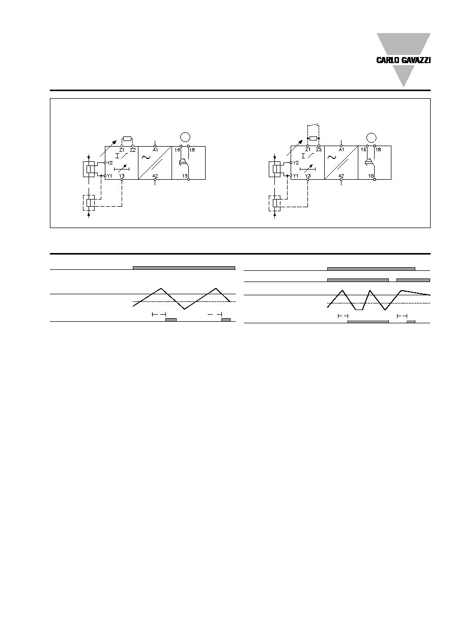
Example 1
(no connection between ter-
minals Z1 & Z2)
The relay operates when the
measured value exceeds the
set level for more than the set
time delay.
The relay releases when the
current (voltage) drops min.
5% below the set level (see
hysteresis) or when power
supply is interrupted.
Example 2
(connection between termi-
nals Z1 & Z2)
The relay operates and latches
in operating position when the
measured value exceeds the
set level for more than the set
time delay.
Provided that the voltage has
dropped min. 5% below the
set point (see hysteresis), the
relay will release when the in-
terconnection between termi-
nals Z1 & Z2 is interrupted, or
power supply is interrupted.
If the measured value is above
the set level when power sup-
ply is applied, the relay will
operate immediately with no
time delay.
The yellow LED is flashing until
the delay has expired or until
the measured value drops
below the fixed hysteresis
(5%) again.
Range/Level/Time Setting
Centre knob:
Current (voltage) level setting
on relative scale.
Lower knob:
Setting of ON delay on abso-
lute scale (0.1-10 s).
Upper knob:
Setting of current (voltage)
range on rotary switch.
When using Y1 & Y3 the scale
is multiplied by 2.
Hysteresis
Normally 5%. The hysteresis
can be extended by inserting
a resistor between terminals
Z1 & Z2.
Approx.
10%: 39 k
25%: 12 k
50%: 4.7 k
75%: 2.2 k
Latch: < 500
Specifications are subject to change without notice
3
T
T
T
T
EIK
Wiring Diagrams
Example 1
Example 2
Measuring range x 2, connect Y1 & Y3.
Measuring range x 2, connect Y1 & Y3.
N
L
µ
X2
(+)
N
L
µ
X2
(+)
X1
I
Measuring range x 1, connect Y1 & Y2.
Hysteresis
adjustment
Measuring range x 1, connect Y1 & Y2.
Latch/Hysteresis adjustment
X1
I
(+)
PE
(+)
PE
Operation Diagrams
Power supply
Set level
Relay ON
Hysteresis
Power supply
Latch ON
Set level
Relay ON
Hysteresis