Specifications are subject to change without notice (15.12.99)
1
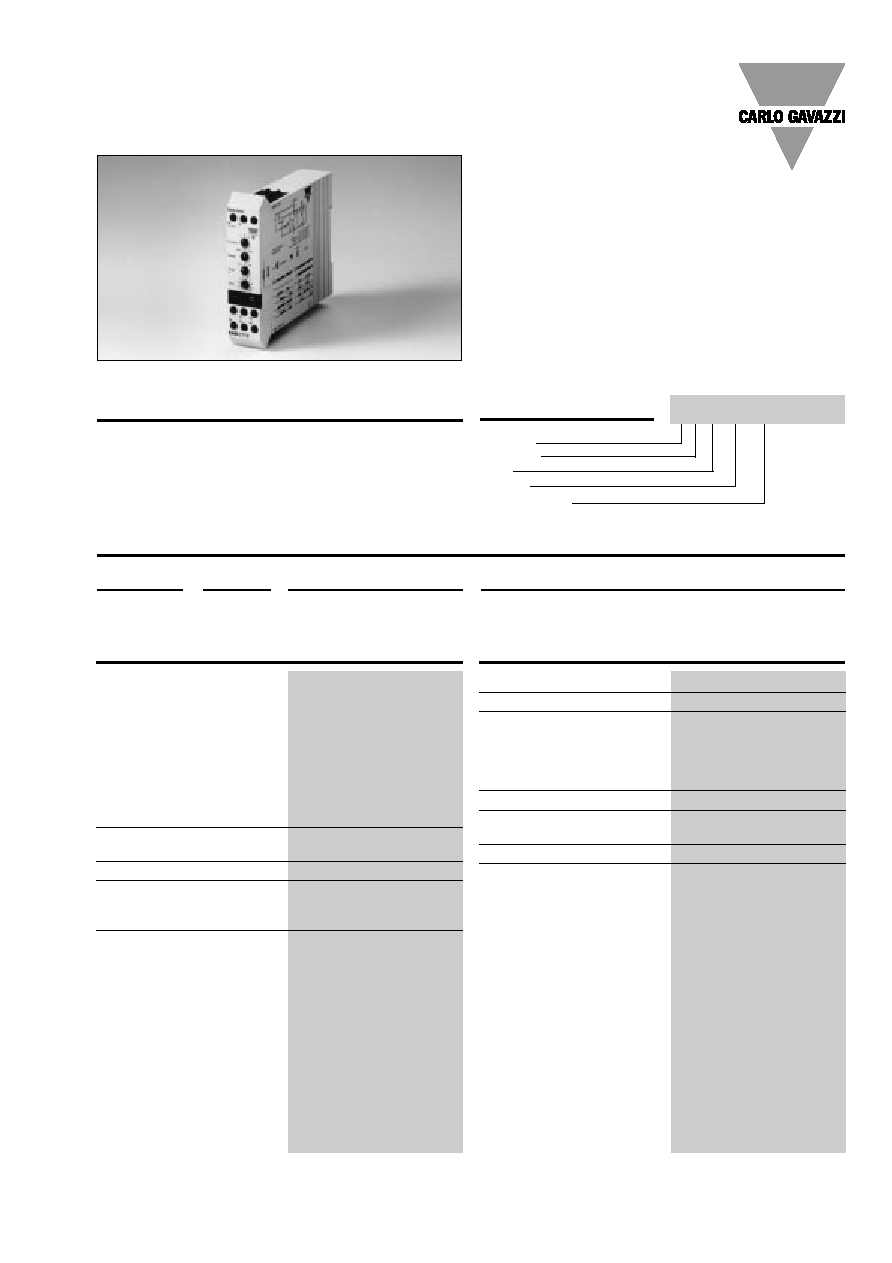
Multi-function
∑ Microprocessor-based quartz timer
∑ Time range 0.1 s to 100 h
∑ Automatic start or pulse start
∑ Knob selection of function and time range
∑ Knob-adjustable time setting
∑ Repeatability deviation:
0.5%
∑ Output: 5 A SPDT
∑ For mounting on DIN-rail in accordance with
DIN/EN 50 022
∑ 22.5 mm Euronorm housing
∑ LED-indication for power supply ON
(flashing when timing)
Product Description
Ordering Key
Housing
Function
Type
Output
Power supply
Type Selection
Mounting
Output
Supply: 12 VDC
Supply: 24 VAC/DC & 115-230 VAC
For DIN-rail
SPDT
EMB C 712
EMB C T23
Extensive applications due to
the combination and variety
of voltages, functions and time
ranges.
Microprocessor-based multi-
function timer with 6 select-
able modes of operation and
time range from 0.1 s to 100 h.
Time Specifications
Time ranges
Selectable by rotary switches
0.1 - 1 s
1 - 10 s
10 - 100 s
0.1 - 1 m
1 - 10 m
10 - 100 m
0.1 - 1 h
1 - 10 h
10 - 100 h
Accuracy
Time accuracy
5%
Repeatability deviation
0.5%
Time variation
Within rated ambient
temperature
0.05%/∞C
Reset
Time and relay
Intercon. pins A1 & Y1
max. voltage = rated
operational voltage, 5 mA
Reaction time
100 ms
Pulse duration
30 ms
Repetition time
250 ms
Output Specifications
Output
SPDT relay
Rated insulation voltage
250 VAC (contact/elect.)
Contact ratings (AgCdO)
µ (micro gap)
Resistive loads
AC 1
5 A, 250 VAC
DC 1
5 A, 24 VDC
Small inductive loads
AC 15
2 A, 250 VAC
DC 13
3 A, 24 VDC
Mechanical life
40 x 10
6
operations
Electrical life
10
5
operations
(at max. load)
Operating frequency
7200 operations/h
Dielectric strength
Dielectric voltage
2 kVAC (rms)
Rated impulse withstand volt.
4 kV (1.2/50 µs)
Type EMB
Timers
EMB C T23

2
Specifications are subject to change without notice (15.12.99)
Supply Specifications
Power supply AC types
Overvoltage cat. III (IEC 60664)
Rated operational voltage
(IEC 60038)
through term. A1 & A2
T23
115-230 VAC, -10/+15%
frequency
50/60 Hz, -5/+5 Hz
through term. A1 & A3
T23
24 VAC/DC, -10/+15%
frequency
50/60 Hz, -5/+5 Hz
Voltage interruption
40 ms
Dielectric voltage
None
Rated impulse withstand
voltage
A1 & A2
4 kV (1.2/50 µs)
A2 & A3
800 V (1.2/50 µs)
Power supply DC types
Rated operational voltage
through term. A1 & A3
12 VDC, -10/+15%
Voltage interruption
40 ms
Dielectric voltage
None
Rated impulse withstand
voltage
A1 & A2
800 V (1.2/50 µs)
Rated operational current
50 mA @ 12 VDC
25 mA @ 24 VDC
40 mA @ 24 VAC
30 mA @ 115 VAC
60 mA @ 230 VAC
General Specifications
EMC
Electromagnetic
Compatibility
Immunity
Acc. to IEC 60801-4
Acc. to IEC 60801-5
Power ON delay
300 ms
Power OFF delay
200 ms
Indication for
Power supply ON
(flashing when timing)
LED, green
Output ON
LED, yellow
Environment
Degree of protection
IP 20
Pollution degree
3
Operating temperature
-10∞ to +50∞C (-14∞ to +122∞F)
Storage temperature
-50∞ to +85∞C (-58∞ to +185∞F)
Weight
200 g
Screw terminals
Tightening torque
Max. 0.5 Nm acc. to IEC 60947
Approvals
UL, CSA
CE-marking
Yes
EMB
Mode of Operation
A1 & Y2 not connected (F)
Function switch in position
1 (delay on operate, pulse
start)
The delay period begins when
power supply is applied and
A1 & Y1 are initiated by a con-
tact.
At the end of the set delay the
relay operates and will not re-
lease until power supply is in-
terrupted for at least 200 ms.
A new time period can be ob-
tained by disconnecting and
subsequently reconnecting
A1 & Y1.
Function switch in position
2 (pulse-controlled interval
timer)
Power supply must be con-
stantly applied.
When A1 & Y1 are initiated by
a contact, the relay operates.
The time period starts when
A1 & Y1 are disconnected.
When interconnecting A1 &
Y1 before the delay has ex-
pired, the time is reset to zero.
The time period restarts when
the interconnection between
A1 & Y1 is interrupted again. A
new time period can be ob-
tained by disconnecting and
subsequently reconnecting A1
& Y1.
Function switch in position
3 (pulse controlled delay on
operate/delay on release)
Power supply must be con-
stantly applied.
The delay period begins when
A1 & Y1 are interconnected.
At the end of the delay period
the relay operates.If A1 & Y1
are disconnected before the
time delay has expired, the
relay operates immediately,
and a new delay period starts.
After this delay the relay re-
leases.
When A1 & Y1 are discon-
nected, a new delay period
starts and when this delay
period has expired, the relay
releases.
If A1 & Y1 are interconnected
before the delay period has
expired, the relay releases im-
mediately, the time is reset to
zero and a new delay period
must expire before the relay
operates.
A1 & Y2 connected (F)
Function switch in position
1 (pulse-started interval ti-
mer, leading edge)
The relay operates and the
time period starts when power
supply is applied and A1 & Y1
are initiated by an impulse or a
contact.
At the end of the set delay the
relay releases. A new time pe-
riod can be obtained by dis-
connecting and subsequently
reconnecting A1 & Y1.
Function switch in position
2 (pulse-started symmetri-
cal recycler, ON-time first)
The relay operates and the
time period starts when power
supply is applied and A1 & Y1
are initiated by an impulse or a
contact.
At the end of the first time pe-
riod the relay releases. When
the second time period (equal
to the first) has expired, the
relay operates.
This sequence continues with
equal ON- & OFF-time peri-
ods until power supply is in-
terrupted.
By applying a new impulse
when the sequence is running,
the sequence will restart.
Function switch in position
3 (pulse-started interval ti-
mer, trailing edge)
When power supply is appli-
ed and A1 & Y1 are intercon-
nected, the relay operates
when A1 & Y1 are disconnec-
ted (triggered on trailing edge)
and the delay period starts.
When the delay period expires,
the relay releases and will not
operate again before A1 & Y1
have been interconnected and
then disconnected.
If A1 & Y1 are interconnected
before the delay period has
expired, the relay releases.
When A1 & Y1 are then dis-
connected again, the relay
operates, and a new delay pe-
riod must expire before the
relay releases again.
