
Specifications are subject to change without notice (08.03.01)
1
Monitoring Relays
3-Phase Load Guard
Type EUF-1
∑ Load guard for asynchronous motors
∑ Measures on phase difference (cos
)
between current and voltage
∑ Two functions: latching or non-latching relay
∑ Internal or external current transformer
∑ Measures on own power supply
∑ Upper and lower cos
level separately
knob-adjustable (cos
0.1-0.99)
∑ Adjustable power ON delay 1-60 s for motor starts
∑ Adjustable time function (0.2-20 s)
∑ Output: 5 A SPDT relay
∑ For mounting on DIN-rail in accordance with
DIN/EN 50 022
∑ 45 mm Euronorm housing
∑ LED-indication for power supply ON
∑ Two LED's indicating fault and/or status of the relay
output (flashing when timing)
Ordering Key
Housing
Function
Type
Output
Power supply
Type
3-phase cos
load guard re-
lay for monitoring the actual
load of asynchronous motors
and other symmetrical loads,
where the cosine to the phase
angle
between current and
voltage is almost proportional
to the load. The relay mea-
sures the angle between motor
current and voltage by using
the built-in or an externally
connected current transformer.
Product Description
Type Selection
Mounting
Output
Supply:
Supply:
Supply:
Supply:
Supply:
220 VAC
400 VAC
480 VAC
600 VAC
690 VAC
For DIN-rail
SPDT
EUF C 220-1
EUF C 400-1
EUF C 480-1
EUF C 600-1
EUF C 690-1
Input Specifications
Input U, V, W
L1-L2-L3
measures on own supply
arbitrary phase sequence
Measuring ranges
Upper level (sep. adjustable)
cos
0.1-0.99
Lower level (sep. adjustable)
cos
0.1-0.99
Internal current transformer
Connect Y1 & Y2
Load current
Through terminals U1 & U2
Measuring range
0.1-6 AAC (rms)
Max. overload current
36 AAC (rms) (max. 20 s)
External current transformer
Standard current transformer Connect Y1 & Y2
Secondary current (1/5 AAC) Through terminals U1 & U2
Type : MI ...
No connection Y1 & Y2
Output signal from CT (MI...) Terminals Y2 & Y3 (0.4-4 V
p
)
(grey wire connected to Y3)
Measuring range
Depending on CT
Output Specifications
Output
SPDT relay
Rated insulation voltage
250 VAC (contact/elect.)
Contact ratings (AgCdO)
µ (micro gap)
Resistive loads
AC 1
5 A, 250 VAC
DC 1
5 A, 24 VDC
Small inductive loads AC 15
2 A, 250 VAC
DC 13
3 A, 24 VDC
Mechanical life
40 x 10
6
operations
Electrical life
10
5
operations
(at max. load)
Operating frequency
7200 operations/h
Dielectric strength
Dielectric voltage
2 kVAC (rms)
Rated impulse withstand volt. 6 kV (1.2/50 µs)
EUF C 400-1

2
Specifications are subject to change without notice (08.03.01)
EUF-1
General Specifications
Supply Specifications
Adjustable delay
0.2 - 20 s
Power ON delay
1 - 60 s
Power OFF delay
1 s
Reaction time
< 200 ms
worst case reaction time
may be up to 5 x
Accuracy
Range
cos
±0.05
Temperature drift
0.1%/∞C (
0.06%/∞F)
Delay
-3/+9 s on max.
0.2 s on min.
Power ON delay
-10/+20 s on max.
1 s on min.
Phase error
(excluding CT phase error)
7∞
Phase error, built-in CT
5∞
Hysteresis
< 3∞
Indication for
Power supply ON
LED, green
Output ON
2 LED's, yellow
(flashing when timing)
Environment
Degree of protection
IP 20
Pollution degree
3
Operating temperature
-20∞ to +50∞C (-4∞ to +122∞F)
Storage temperature
-50∞ to +85∞C (-58∞ to +185∞F)
Weight
420 g
Screw terminals
Tightening torque
Max. 0.5 Nm acc. to IEC 60947
Approvals
UL, CSA
CE Marking
Yes
Power supply
Overvoltage cat. III (IEC 60664)
Rated operational voltage
(IEC 60038)
Through term. U, V, W 220
220 VAC, ±15%
50/60 Hz, -5/+5 Hz
400
400 VAC, ±15%
50/60 Hz, -5/+5 Hz
480
480 VAC, ±15%
50/60 Hz, -5/+5 Hz
600
600 VAC, ±15%
50/60 Hz, -5/+5 Hz
690
690 VAC, ±15%
50/60 Hz, -5/+5 Hz
Voltage interruption
40 ms
Dielectric voltage
None
Rated impulse withstand
voltage
up to 480 VAC
4 kV (1.2/50 µs)
up to 690 VAC
6 kV (1.2/50 µs)
Rated operational power
3 VA
Supplied from
L2 & L3
Mode of Operation
EUF-1 can be used for moni-
toring the actual load of asyn-
chronous motors.
The relay measures cosine to
the angle between motor cur-
rent and motor voltage (cos
).
As cos
varies with the load
of the motor, underload and
overload can be detected in-
directly by EUF-1.
The relation between the load
and cos
depend on the type
of motor. As a guideline to
ensure correct working condi-
tions for a motor, the upper
level could be set above the
cos
marking on the motor,
and the lower level under. It is
recommended to make the
adjustment in connection with
a practical test.
The relay has a power ON
delay in order to allow over-
load during motor start.
Example 1
Latching mode
(Y3 & Z1 not connected)
In this application the EUF-1
is connected to an external
current metering transformer,
type MI..., (no connection be-
tween Y1 & Y2) as well as to a
3-phase asynchronous motor.
The EUF-1 operates and the
relay is energized when the
power supply is applied. After
the power ON delay, the EUF-
1 starts to measure cos
. If
cos
is within the two adjust-
ed levels, the relay will be
kept energized, and the two
level LED's will emit continuous
light. If not, then the output
relay will release after the set
time has expired. To restart
the cos
measurement, con-
nect Y3 & Z1 or interrupt the
power supply for at least 1 s
before it is reapplied.
Example 2
Non-latching mode
(Y3 & Z1 connected)
The EUF-1 will react as de-
scribed in example 1 except:
the relay will reactivate auto-
matically when cos
is within
the two adjusted levels again.
The level is indicated by the
two built-in yellow LED's.
When the measured cos
rises above the adjusted
upper level, then the centre
LED starts to flash, and the
output relay releases after the
set time period. When the
measured cos
drops below
the adjusted lower level, then
the left LED starts to flash,
and the output relay releases
after the set time period.
When the output relay is re-
leased, there will be no LED
indication.
Specifications are subject to change without notice (08.03.01)
3
EUF-1
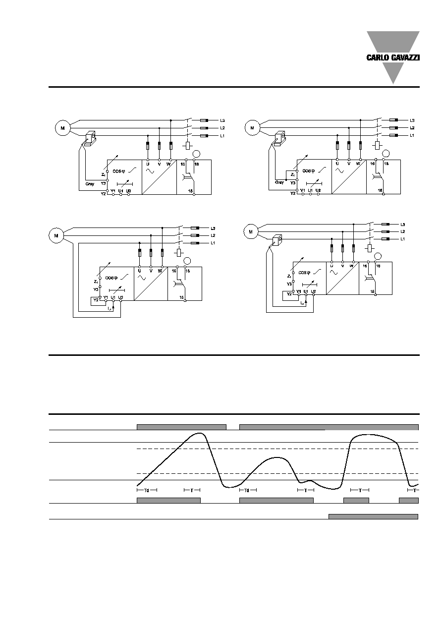
Wiring Diagrams
Example 2 (MI CT, non-latching mode)
Level setting
Upper left knob:
Setting of upper limit on abso-
lute scale (0.1-0.99).
Level/Time Setting
Lower left knob:
Setting of lower limit on abso-
lute scale (0.1-0.99).
Time setting
Lower right knob:
Setting of time delay for both
upper and lower limit (0.2-20 s).
Upper right knob:
Setting of time power ON delay
(1-60 s).
Operation Diagram
Power supply
Upper level
Hysteresis
Hysteresis
Lower level
Cos
Relay 1
Y3 & Z1 connected
Example 1 (MI CT, latching mode)
Example 3 (Internal CT, latching mode)
Example 4 (Standard CT, latching mode)
µ
µ
µ
µ