Specifications are subject to change without notice
1
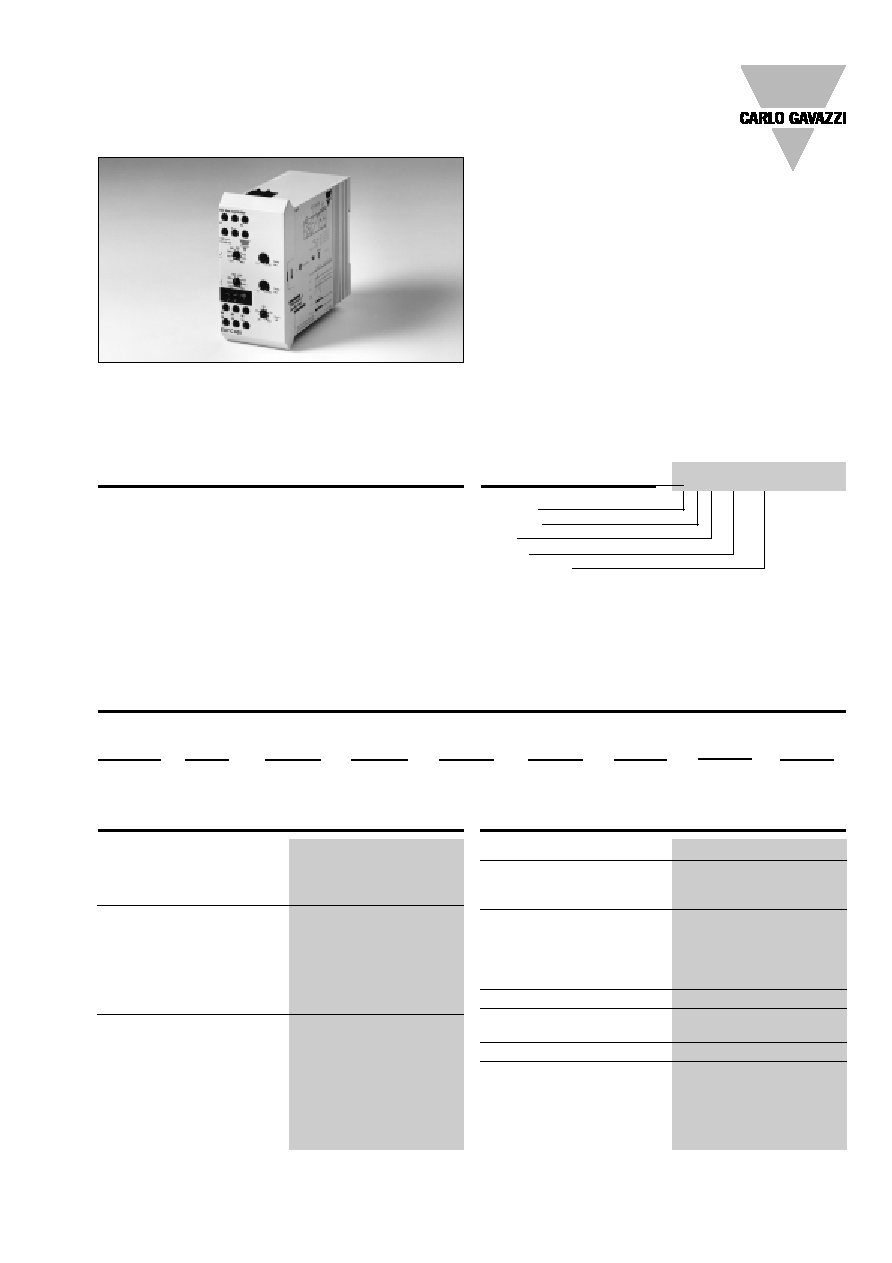
Current and Voltage Controls
Type EUY
∑ True RMS measuring on own power supply
∑ Frequency range 45-440 Hz
∑ Monitoring relay and 3-phased measuring relay for
over/under voltage control (closed circuit)
∑ Monitors phase asymmetry
∑ Monitors phase loss/phase sequence
∑ Measures if all 3 phase-phase voltages are within
set limits
∑ Upper and lower limits separately adjustable
∑ Adjustable asymmetry
∑ 2 separately adjustable time functions (0.1-30 s)
∑ Output: 2 x 5 A SPDT relays (one relay for each level)
∑ For mounting on DIN-rail in accordance with
DIN/EN 50 022
∑ 45 mm Euronorm housing
∑ LED-indication for power supply ON
∑ Two LED's indicating fault and/or status of the
2 relay outputs (flashing when timing)
3-Phase True RMS, Multi-Function
Product Description
Ordering Key
Housing
Function
Type
Output
Power supply
True rms 3-phase monitoring
relay for separate over and un-
der voltage, asymmetry and
phase failure control. The
advantage of true rms meas-
uring is that correct values are
always obtained irrespective
of the waveform of the meas-
ured voltage, i.e. the EUY
measures the correct rms
value of a normal sinusoidal
power supply as well as of a
distorted power supply. Fre-
quency range 45 to 440 Hz.
With relays measuring aver-
age value (EUB, EUC) correct
values are only obtained for
true sinusoidal power sup-
plies. Often used in motor ap-
plications where it is impor-
tant to detect the reliability of
the electrical power.
Type Selection
Mounting
Output
Supply:
Supply: Supply: Supply:
Supply:
Supply:
Supply:
115 VAC
220 VAC
240 VAC
400 VAC
480 VAC
600 VAC
690 VAC
For DIN-rail
2 x SPDT
EUY C 115
EUY C 220
EUY C 240
EUY C 400
EUY C 480
EUY C 600
EUY C 690
Input Specifications
Input U, V, W
L1 - L2 - L3
measures on own supply
phase sequence not arbitrary
Frequency range
45-440 Hz
Measuring ranges
115
92-132 VAC
(True rms)
220
176-253 VAC
240
192-276 VAC
400
320-460 VAC
480
384-552 VAC
600
480-690 VAC
690
552-794 VAC
Range
Upper level (sep. adjustable)
80 - 115%
Lower level (sep. adjustable)
80 - 115%
Asymmetry (sep. adjustable)
5-25% of nominal range
Phase loss (phase-phase)
70% of nominal range
Output Specifications
Output
2 x SPDT relay
Rated insulation voltage
250 VAC (contact/elect.)
Upper limit
Terminals 25/26/28
Lower limit
Terminals 15/16/18
Contact ratings (AgCdO)
µ (micro gap)
Resistive loads
AC 1
5 A, 250 VAC
DC 1
5 A, 24 VDC
Small inductive loads AC 15
2 A, 250 VAC
DC 13
3 A, 24 VDC
Mechanical life
40 x 10
6
operations
Electrical life
10
5
operations
(at max. load)
Operating frequency
7200 operations/h
Dielectric strength
Dielectric voltage
2 kVAC (rms)
Rated impulse withstand volt. 4 kV (1.2/50 µs)
EUY C 400
2
Specifications are subject to change without notice
EUY
General Specifications
Power ON delay
3 s
Reaction time
Switching out
1. priority error
1.5 s
2. priority error
3.0 s
Switching in
4.0 s
Accuracy
Range
5%
Temperature drift
0.1%/∞C
Delay (upper/lower level)
30 s, ±5% on max.
< 0.1 s on min.
Temperature drift
0.05%/∞C (
0.06%/∞F)
Hysteresis
Level
< 2.0%
Asymmetry
< 3.0%
Indication for
Power supply ON
LED, green
Output/error condition
2 x LED's, yellow
(see LED table)
Environment
Degree of protection
IP 20
Pollution degree
3
Operating temperature
-10∞ to +50∞C (-4∞ to +122∞F)
Storage temperature
-50∞ to +85∞C (-58∞ to +185∞F)
Weight
280 g
Screw terminals
Tightening torque
Max. 0.5 Nm acc. to IEC 60947
Approvals
UL, CSA
Supply Specifications
Power supply
Overvoltage cat. III (IEC 60664)
Rated operational voltage
(IEC 60038)
Through term. U, V, W 115
115 VAC, -20/+15%
45-440 Hz
220
220 VAC, -20/+15%
45-440 Hz
240
240 VAC, -20/+15%
45-440 Hz
400
400 VAC, -20/+15%
45-440 Hz
480
480 VAC, -20/+15%
45-440 Hz
600
600 VAC, -20/+15%
45-440 Hz
690
690 VAC, -20/+15%
45-440 Hz
Voltage interruption
40 ms
Dielectric voltage
None
Rated impulse withstand
voltage
up to 480 VAC
4 kV (1.2/50 µs)
up to 690 VAC
6 kV (1.2/50 µs)
Rated operational power
5 VA
Supplied from
L1, L3
Mode of Operation
Connected to the 3 phases, the
EUY operates and the two out-
put relays are energized when
all three phases are present at
the same time, the phase se-
quence is correct, the mea-
sured asymmetry is below set
value and the 3 phase-phase
voltages are within set limits.
This is indicated by the two
LED's. If one or more of the
phase-phase voltages rises
above, or if the measured
asymmetry exceeds the set
level, then the centre (yellow)
LED starts to flash, and the
output relay (terminals 25/26/
28) releases after the set time
period. If one or more of the
phase-phase voltages drops
below the set level, then the
left (yellow) LED starts to flash,
and the output relay (termi-
nals 15/16/18) releases after
the set time period. If the phase
sequence is wrong or one
phase is lost, then the two
built-in output relays will re-
lease immediately. No time
function will occur. The failure
will be indicated by the two
yellow LED's. At phase loss
both LED's will flash. At wrong
phase sequence the LED's will
flash alternately (see LED ta-
ble).
Example 1
Mains network monitoring
The relay monitors over and
under voltage, phase loss, cor-
rect phase sequence and that
the phase asymmetry is within
the adjusted level.
Example 2
Starting and operating load
monitoring
The EUY ensures correct start-
ing and operating conditions.
The relay controls the voltage
level, phase sequence, asym-
metry and the correct direc-
tion of motor rotation.
Frequent failures are fuse
blowing, asymmetry, and incor-
rect voltage level. In case of
fuse blowing the motor will re-
generate a voltage in the inter-
rupted phase. The EUY will
detect the failure and react
immediately due to excessive
imbalance between the phases.
Asymmetry/Level/Time Setting
Time 1 setting (lower level)
Centre right knob:
Setting of time delay on abso-
lute scale (0.1-30 s).
Time 2 setting (upper level)
Upper right knob:
Setting of time delay on abso-
lute scale (0.1-30 s).
Asymmetry setting
Lower right knob:
Setting of asymmetry level on
absolute scale.
Level setting
Upper left knob:
Setting of upper limit on abso-
lute scale.
Lower left knob:
Setting of lower limit on abso-
lute scale.

Specifications are subject to change without notice
3
Phase sequence
Switches
Switches
No time delay
Both LED's flash alternately.
Both LED's flash alternately.
Remains
If phase sequence
OFF
OFF
Frequency 3 Hz.
Frequency 3 Hz.
ON
is wrong
Wiring Diagrams
Example 1
Example 2
µ
µ
Table for Relay Position and LED-indication
Failure
Relay for
Relay for
Time
Left yellow LED (1)
Centre yellow LED (2)
Right green LED
lower level
upper level
delay
for lower level
for upper level
for power ON
term. 15/16/18
term. 25/26/28
indication
indication
indication
The voltage
Remains
Switches
Time 2 UL
Remains
LED starts flashing (during the time period)
Remains
rises above
ON
OFF
Time delay
ON
when the measured voltage exceeds the set
ON
the UL set value
Adj. 0.1-30 s
value. Frequency 1 Hz. Switches off after delay.
The voltage
Switches
Remains
Time 1 LL
LED starts flashing (during the time period)
Remains
Remains
drops below
OFF
ON
Time delay
when the measured voltage drops below the set
ON
ON
the LL set value
Adj. 0.1-30 s
value. Frequency 1 Hz. Switches off after delay.
Asymmetry
Remains
Switches
Time 2 UL
Switches
LED starts flashing (during the time period)
Remains
exceeds set level
ON
OFF
Time delay
OFF
when the measured asymmetry exceeds the set
ON
Adj. 0.1-30 s
value. Frequency 8 Hz. Switches off after delay.
Phase loss
Switches
Switches
No time delay
Both LED's flash in phase. Frequency 3 Hz.
Both LED's flash in phase. Frequency 3 Hz.
Remains
voltage drops below
OFF
OFF
If L2 or L3 are lost no LED indication will
If L2 or L3 are lost no LED indication will
ON
70% of nom. range
occur. (L2 and L3 are supplying the system).
occur. (L2 and L3 are supplying the system).
EUY
Operation Diagram
Upper level
Hysteresis
Hysteresis
Lower level
Asymmetry
Hysteresis
U
L1
V
L2
W
L3
Relay 2 upper (25/26/28)
Relay 1 lower (15/16/18)
L2-L3
L1-L2
L1-L3
Overlapping
Switches
Switches
No time delay
Indicating actual fault.
Indicating actual fault.
Green LED starts flashing.
of LL and UL
OFF
OFF
Frequency 3 Hz.
set level