Specifications are subject to change without notice (01.09.99)
1
Dupline
Æ
Field- and Installationbus
Type: Dupline
Output signal
Supply
Ordering Key
∑ Receivers with current signal output
∑ Current output signals:
FAD 1530: 1 x 0 to 1 mA
FAD 1531: 1 x 0 to 20 mA
FAD 1532: 1 x 4 to 20 mA
∑ 8-bit (8 channels) resolution
∑ For binary transmitted analogue signals
∑ Galvanically separated output
∑ D-housing
∑ Plug-in type module
∑ AC power supply
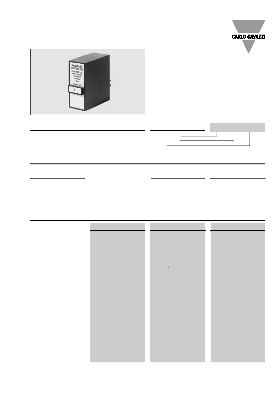
Product Description
Dupline analog receivers with
standard current output sig-
nals (0 to 1 mA, 0 to 20 mA, 4
to 20 mA). Convert binary
codes into analog current sig-
nals.
Type Selection
Supply
Ordering no.
Ordering no.
Ordering no.
0 to 1 mA
0 to 20 mA
4 to 20 mA
24 VAC
FAD 1530 024
FAD 1531 024
FAD 1532 024
120 VAC
FAD 1530 120
FAD 1531 120
FAD 1532 120
220 VAC
FAD 1530 220
FAD 1531 220
FAD 1532 220
Code module
FMK A to FMK P
FMK A to FMK P
FMK A to FMK P
Output Specifications
FAD 1530 ...
FAD 1531 ...
FAD 1532 ...
Output
1 current output
1 current output
1 current output
Signal range
0 to 1 mA
0 to 20 mA
4 to 20 mA
Isolated in groups of
1 x 1
1 x 1
1 x 1
Output load resistance
10 k
350
350
Resolution
8 bits (3.92 µA/LSB)
8 bits (78.43 µA/LSB)
8 bits (62.75 µA/LSB)
Settling time
1 pulse train + 10 ms
1 pulse train + 10 ms
1 pulse train + 10 ms
Short-circuit protection
Yes
Yes
Yes
Short-circuit current
1 mA
20 mA
20 mA
Open loop voltage
Approx. 15 V
Approx. 15 V
Approx. 15 V
Inaccuracy
1% of full scale
1% of full scale
1% of full scale
Cable length
3 m
3 m
3 m
Dielectric voltage
Output - Dupline
200 VAC (rms)
200 VAC (rms)
200 VAC (rms)
Receiver with Analog Current Output
Types FAD 1530, FAD 1531, FAD 1532
FAD 1530 024
2
Specifications are subject to change without notice (01.09.99)
Supply Specifications
FAD 1530, FAD 1531, FAD 1532
General Specifications
Power supply
Overvoltage cat. III (IEC 60664)
Rated operational voltage
through pins A1 & A2 220
230 VAC +6%,
-15% (IEC 60038)
120
120 VAC ± 10% (IEC 60038)
024
24 VAC ± 10%
Frequency
45 to 65 Hz
Voltage interruption
40 ms
Rated operational power
Typ. 2.5 VA
Rated impulse
220
4 kV
withstand voltage
120
2.5 kV
024
800 V
Dielectric voltage
Supply - Dupline
2 kVAC (rms)
Supply - Output
2 kVAC (rms)
Output OFF delay
upon loss of Dupline carrier
Undefined
Power ON delay
Undefined,
1 s
Environment
Degree of protection
IP 20
Pollution degree
3 (IEC 60664)
Operating temperature
-20∞ to +50∞C (-4∞ to +122∞F)
Storage temperature
-50∞ to +85∞C (-58∞ to +185∞F)
Humidity (non-condensing)
20 to 80%
Mechanical resistance
Shock
15 G (11 ms)
Vibration
2 G (6 to 55 Hz)
Dimensions
Material
(see "Technical Information")
D-housing
Weight
200 g
Approvals
CSA, UL
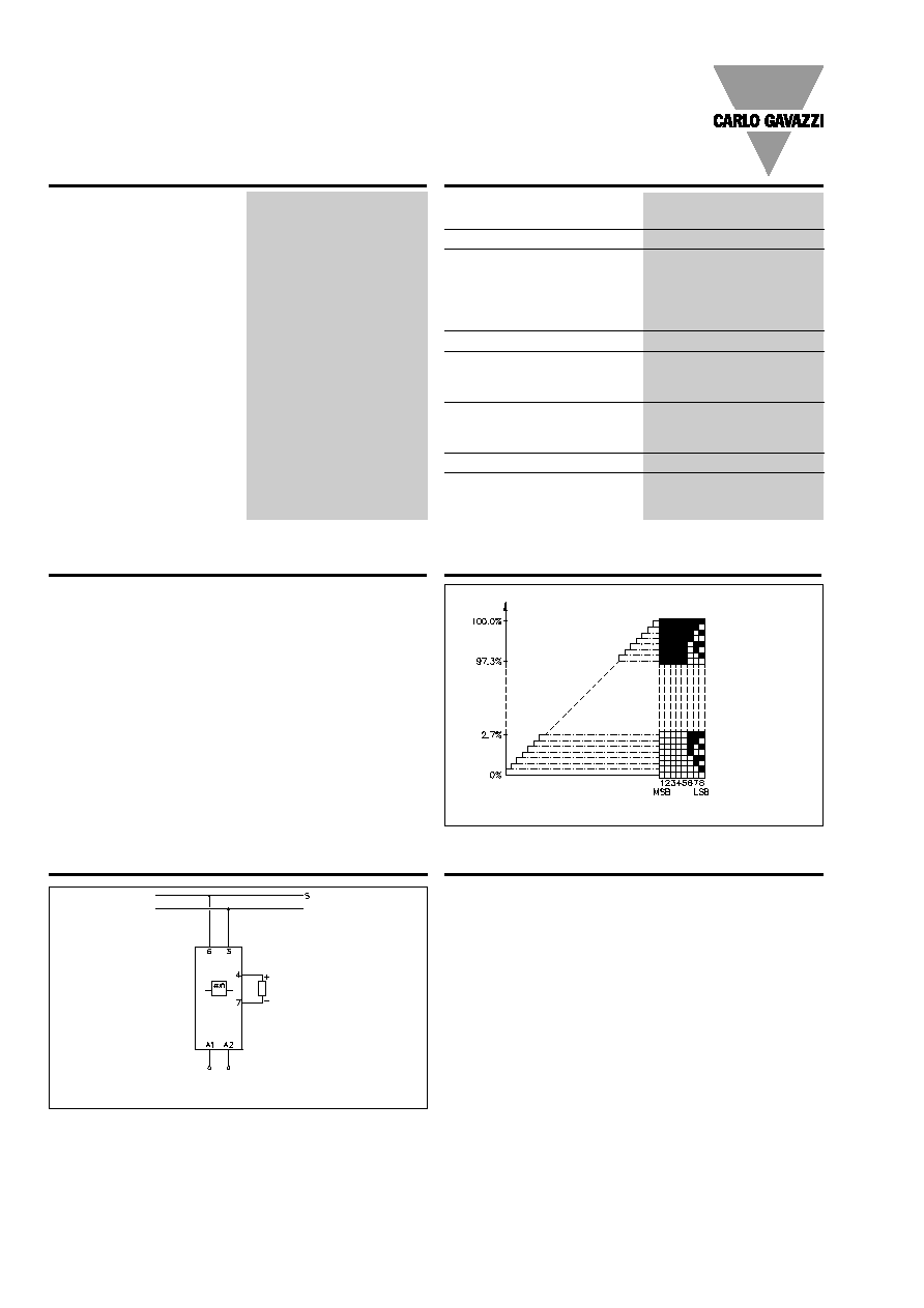
Operation Diagram
Mode of Operation
Receiver with current signal
output. The binary status of
an entire channel group (8 bit)
is converted to a current sig-
nal. The binary status of the
selected group may be gen-
erated by Dupline transmit-
ters with analog inputs (cur-
rent, voltage, temperature
etc.) or by PC's.
The least significant bit (influ-
encing the output current by
0.392% of full scale) is the
highest channel of the select-
ed group (C8 if FMK C is
plugged in). The most signifi-
cant bit (influencing the output
current by 49.8% of full scale)
is the lowest channel of the
selected group (C1 in the
above example).
Note: Analog receivers must
not be used in systems where
channel generators with 2 or 3
sequences are installed.
Output
signal
Accessories
Socket
D 411
Socket cover
BB 5
Hold down spring
HF
Front mounting bezel
FRS 2
DIN-rail for D 411
FMD 411
For further information refer to "Accessories".
Wiring Diagram
Load
S: signal wire.
MSB =
Most Significant Bit
LSB =
Least Significant Bit
Channel status
Power
Supply