Specifications are subject to change without notice (01.09.99)
1
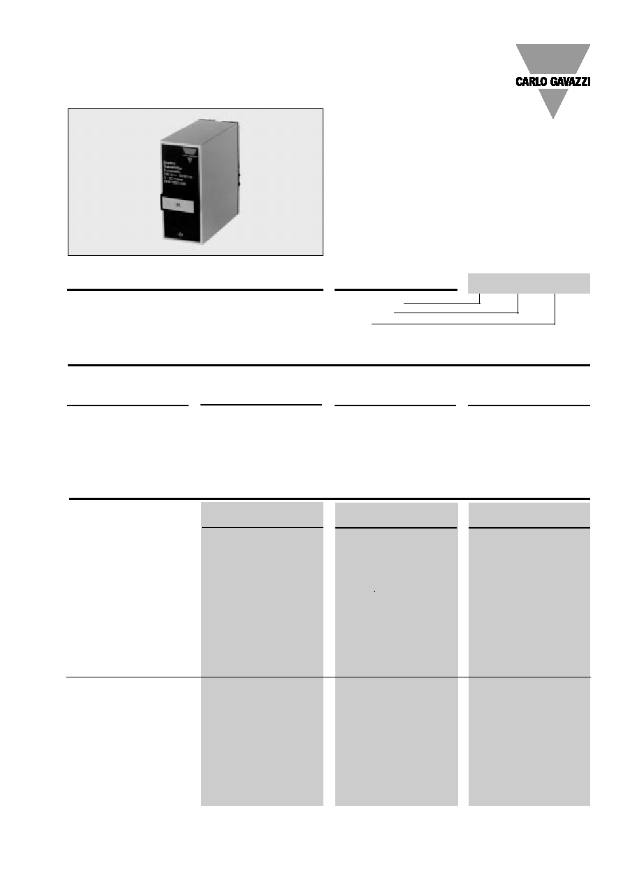
Dupline
Æ
Field- and Installationbus
Transmitter for Analog Current Signals
Types FFD 1530, FFD 1531, FFD 1532
∑ Transmitter with current input
∑ Current input signals:
FFD 1530: 1 x 0 to 1 mA
FFD 1531: 1 x 0 to 20 mA
FFD 1532: 1 x 4 to 20 mA
∑ 8-bit (8 channels) resolution
∑ Binary transmission
∑ Enable input function
∑ D-housing
∑ Plug-in type module
∑ AC power supply
Supply
Ordering no.
Ordering no.
Ordering no.
1 signal
1 signal
1 signal
0 to 1 mA
0 to 20 mA
4 to 20 mA
24 VAC
FFD 1530 024
FFD 1531 024
FFD 1532 024
120 VAC
FFD 1530 120
FFD 1531 120
FFD 1532 120
220 VAC
FFD 1530 220
FFD 1531 220
FFD 1532 220
Code module
FMK A to FMK P
FMK A to FMK P
FMK A to FMK P
Input Specifications
Product Description
Type Selection
Type: Dupline
Input signal
Supply
Dupline transmitters for ex-
ternal supply. Standard cur-
rent signal input (0 to 1 mA,
0 to 20 mA, 4 to 20 mA).
Convert analog current sig-
nals into binary codes.
Ordering Key
FFD 1530 ...
FFD 1531 ...
FFD 1532 ...
(8 channels)
(8 channels)
(8 channels)
Signal input
1 current input
1 current input
1 current input
Signal range
0 to 1 mA
0 to 20 mA
4 to 20 mA
Zero adjustment (X
1
)
None
None
None
Span adjustment (X
2
)
None
None
None
Span
None
None
None
Input resistance
470
47
47
Resolution
8 bits (3.92 µA/LSB)
8 bits (78.43 µA/LSB)
8 bits (62.75 µA/LSB)
Settling time
1 pulse train + 10 ms
1 pulse train + 10 ms
1 pulse train + 10 ms
Open circuit monitoring
None
None
None
Inaccuracy (ref. temp. 20∞C)
of full scale
1%
1%
1%
Cable length
3 m
3 m
3 m
Dielectric voltage
Input - Dupline
200 VAC (rms)
200 VAC (rms)
200 VAC (rms)
Transmission enable input
1 contact or NPN transistor
1 contact or NPN transistor
1 contact or NPN transistor
Open loop voltage
5 VDC
5 VDC
5 VDC
Short-circuit current
1 mA
1 mA
1 mA
Operating time for signal "1"
1 pulse train + 10 ms
1 pulse train + 10 ms
1 pulse train + 10 ms
Operating time for signal "0"
1 pulse train + 10 ms
1 pulse train + 10 ms
1 pulse train + 10 ms
Contact resistance
100
100
100
Cable length
3 m
3 m
3 m
Dielectric voltage
Input- Dupline
200 VAC (rms)
200 VAC (rms)
200 VAC (rms)
FFD 1530 024

2
Specifications are subject to change without notice (01.09.99)
FFD 1530, FFD 1531, FFD 1532
Supply Specifications
General Specifications
Power supply
Overvoltage cat. III (IEC 60664)
Rated operational voltage
through pins A1 & A2 220
230 VAC +6%, -15% (IEC 60038)
120
120 VAC ± 10% (IEC 60038)
024
24 VAC ± 10%
Frequency
45 to 65 Hz
Voltage interruption
40 ms
Rated operational power
Typ. 2.5 VA
Rated operational
withstand voltage
220
4 kV
120
2.5 kV
024
800 V
Dielectric voltage
Supply - Dupline
2 kVAC (rms)
Supply - Signal input
2 kVAC (rms)
Supply - Enable input
2 kVAC (rms)
Power ON delay
Undefined,
1 s
Environment
Degree of protection
IP 20 B
Pollution degree
3 (IEC 60664)
Operating temperature
-20∞ to +50∞C (-4∞ to +122∞F)
Storage temperature
-50∞ to +85∞C (-58∞ to +185∞F)
Humidity (non-condensing)
20 to 80%
Mechanical resistance
Shock
15 G (11 ms)
Vibration
2 G (6 to 55 Hz)
Dimensions
Material
(see "Technical Information")
D-Housing
Weight
200 g
Approvals
UL
Wiring Diagram
S: signal wire.
Mode of Operation
Transmitters with current sig-
nal input. The current signal
is converted into a binary
value represented as the bi-
nary status of an entire chan-
nel group (8 bit). This binary
value may be reconverted into
current or voltage signals
through receivers with ana-
logue outputs (type FAD 15..)
or displayed in a scaled 7-
segment display via D 6369
6475.
A signal change of 0.392% of
full scale influences the least
significant bit, which is the
highest channel of the se-
lected group (F8 if FMK F is
plugged in). A signal change
of 49.8% of full scale influ-
ences the most significant bit
or the lowest channel of the
selected group (F1 in the
above example).
No value is transmitted un-
less the transmission enable
input is activated (pins 5 and
7 connected). This input may
also be used to transmit up to
255 individual values on one
channel group by using Dup-
line receivers with demultiplex
output type D 1230 5111.
Note:
Analog transmitters
must not be used in systems
where channel generators
with 2 or 3 sequences are in-
stalled.
Accessories
Socket
D 411
Socket cover
BB 5
Hold down spring
HF
Front mounting bezel
FRS 2
DIN-rail for D 411
FMD 411
For further information refer to "Accessories".
Operation Diagram
Input
Signal
Channel status
MSB =
Most Significant Bit
LSB =
Least Significant Bit
Transmission Enable
Common
Input
Power Supply