
Specifications are subject to change without notice (01.09.99)
1
Supply
Ordering no.
1 signal
0 to 10 VDC
24 VAC
FFD 1533 024
120 VAC
FFD 1533 120
220 VAC
FFD 1533 220
Code module
FMK A to FMK P
Dupline
Æ
Field- and Installationbus
Transmitter for Analog Voltage Signals
Type FFD 1533
Dupline transmitters for ex-
ternal supply. For connection
to signal converters with
standard voltage output (0 to
10 V). Converts analog volt-
age signals into binary codes.
Type: Dupline
Input signal
Supply
Product Description
Ordering Key
∑ Transmitter with voltage input
∑ Voltage input signal: 1 x 0 to 10 VDC
∑ 8-bit (8 channels) resolution
∑ Binary transmission
∑ Enable input function
∑ D-housing
∑ Plug-in type module
∑ AC power supply
Type Selection
Input/Output Specifications
Reference output
1 voltage output
Output voltage U
R
through pins 7 & 8
10 VDC (none regulated)
Output load resistance
5 k
Short-circuit protection
none
Output current
2 mA
Cable length
3 m
Dielectric voltage
Output - Dupline
None
FFD 1533 024
Signal input
1 voltage input
Signal range
0 to 10 VDC
Zero adjustment (X
1
)
None
Span adjustment (X
2
)
None
Span
None
Input resistance
100 k
Resolution
8 bits (39.22 mV/LSB)
Settling time
1 pulse train + 10 ms
Open circuit monitoring
None
Inaccuracy (ref. temp. 20∞C)
of full scale
1%
Cable length
3 m
Dielectric voltage
Input - Dupline
200 VAC (rms)
Transmission enable input
1 contact or NPN transistor
Open loop voltage
5 VDC
Short-circuit current
1 mA
Operating time for signal "1"
1 pulse train + 10 ms
Operating time for signal "0"
1 pulse train + 10 ms
Contact resistance
100
Cable length
3 m
Dielectric voltage
Input - Dupline
200 VAC (rms)
2
Specifications are subject to change without notice (01.09.99)
Power supply
Overvoltage cat. III (IEC 60664)
Operational voltage
through pins A1 & A2 220
230 VAC +6%, -15% (IEC 60038)
120
120 VAC ± 10% (IEC 60038)
024
24 VAC ± 10%
Frequency
45 to 65 Hz
Voltage interruption
40 ms
Rated operational power
typ. 2.5 VA
Rated operational
withstand voltage
220
4 kV
120
2.5 kV
024
800 V
Dielectric voltage
Supply - Dupline
2 kVAC (rms)
Supply - Signal input
2 kVAC (rms)
Supply - Enable input
2 kVAC (rms)
Supply - Reference output
2 kVAC (rms)
FFD 1533
Power Specifications
General Specifications
Power ON delay
Undefined,
1 s
Environment
Degree of protection
IP 20
Pollution degree
3 (IEC 60664)
Operating temperature
-20∞ to +50∞C (-4∞ to +122∞F)
Storage temperature
-50∞ to +85∞C (-58∞ to +185∞F)
Humidity (non-condensing)
20 to 80%
Mechanical resistance
Shock
15 G (11 ms)
Vibration
2 G (6 to 55 Hz)
Dimensions
Material
(see "Technical Information")
D-Housing
Weight
200 g
Approvals
UL
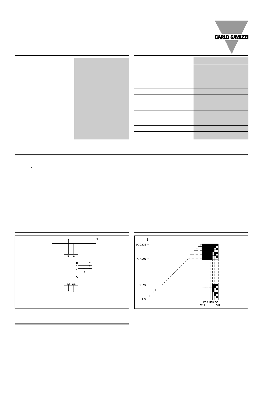
Mode of Operation
Wiring Diagram
Transmitter with voltage sig-
nal input. The voltage signal
is converted into a binary
value represented as the bi-
nary status of an entire
channel group (8 bit). This
binary value may be recon-
verted into current or volta-
ge signals through receivers
with analogue outputs (type
FAD 15..) or displayed as a
scaled 7-segment display
via D 6369 6475.
A signal change of 0,392%
of full scale influences the
least significant bit, which is
the highest channel of the
selected group (J8 if FMK J
is plugged in). A signal
change of 49.8% of full sca-
le influences the most sig-
nificant bit or the lowest
channel of the selected gro-
up (J1 in the above example).
No value is transmitted un-
less the transmission enable
input is activated (pins 5 and
7 connected). This input
may also be used to trans-
mit up to 255 individual
values on one channel gro-
up by using Dupline recei-
vers with demultiplex output
type D 1230 5111.
The 10 VDC reference out-
put (pins 8 and 7) is a useful
feature to supply for instan-
ce a potentiometer whose
signal may represent physi-
cal parameters, e.g. shutter
position, opening angle etc.
Note: Analog transmitters
must not be used in systems
where channel generators
with 2 or 3 sequences are
installed.
Power Supply
U
R
Input
Common
S: signal wire.
Operation Diagram
Input
Signal
Accessories
Socket
D 411
Socket cover
BB 5
Hold down spring
HF
Front mounting bezel
FRS 2
DIN-rail for D 411
FMD 411
For further information refer to "Accessories".
Channel status
LSB =
Least Significant Bit
MSB =
Most Significant Bit
Transmission Enable