
Du line
Æ
Fieldbus
Installationbus
Specifications are subject to change without notice (28.04.03)
1
Dupline
Æ
is a registered trademark. A product of the CARLO GAVAZZI Group
∑ 4-channel transmitter + 1-ch. Receiver (Built-in red
LED output)
∑ 4 contact or NPN transistor inputs
∑ LED-indications for supply and Dupline
Æ
carrier
∑ LED-indication for armed when using Dupline
Æ
supply
∑ 3-wire system with Dupline
Æ
and supply of module
through G 3485 0000, G 3496 000X or G 2196 000X
∑ Channel coding by GAP 1605
∑ Open PCB with terminal connection
∑ Bracket for DIN-rail mounting available
Product Description
Ordering Key
Type: Dupline
Æ
Open PCB
Input Module
Number of Inputs
Input Type
DC Supply
Type Selection
Supply
Ordering no.
Contacts/NPN transistors
10-30 VDC or supplied by Dupline
Æ
G 2110 4401 700
G 2110 4401 700
Input Specifications
Supply Specifications
Input module
Inputs
4 contact or NPN-transistor
Open loop voltage
8.0 VDC
Open loop voltage
Dupline
Æ
supplied 5,3-7,6 VDC
Short-circuit current
100 µA
Input voltage signal "1"
2 V
Input voltage signal "0"
5,5 V
Contact resistance
< 1 k
Cable length
< 3 m
Response time
1 pulse train
(156 ms @ 128 channels)
3-wire supply specifications
Power supply DC types
Overvoltage cat III (IEC 60664)
Rated operational voltage (VDD
in
) 10-30 VDC (ripple included)
Ripple
3 V
Reverse polarity protection
Yes
Current consumption
15 mA + load on DC+
Max. load on DC+
250 mA
Inrush current
1 A
Power dissipation
0.5 W
Transient protection voltage
800 V
Dieelectric voltage:
Supply ≠ Dupline
Æ
None
Supply ≠ Inputs
None
Dupline
Æ
supply specifications
Current consumption
2 mA
Type G 2110 4401
Dupline
Æ
input module with 4
contact/NPN transistor in-
puts, specially designed as a
part of the Dupline
Æ
alarm
concept for contact moni-
toring. The module can be
used in connection with
G 2196 000X, G3496 000X or
G 3485 0000, which have
Dupline
Æ
pulse controlled
output. The module offers
installer-friendly mounting
and reliable operation and
can be installed and main-
tained without the need for
special tools or programming
knowledge.
General Specifications
Power ON delay
Typ. 2 s
Indication for
(only 3-wire applications)
(No indication when
supplied by Dupline
Æ
)
Supply ON
LED, green
Dupline
Æ
carrier
LED, yellow
Armed
LED, red
Environment
Operating temperature
-20 to +50∞C (-4 to +122∞F)
Storage temperature
-50 to +85∞C (-58 to +185∞F)
Humidity (non-condensing)
20 ≠ 80%
Mechanical resistance
Shock
15 G (11 ms)
Vibration
2 G (6 to 55 Hz)
Dimensions
Open PCB 58 x 46 mm
Weigth
50 g
Du line
Æ
Fieldbus
Installationbus
2
Specifications are subject to change without notice (28.04.2006)
Dupline
Æ
is a registered trademark. A product of the CARLO GAVAZZI Group
Mode of Operation
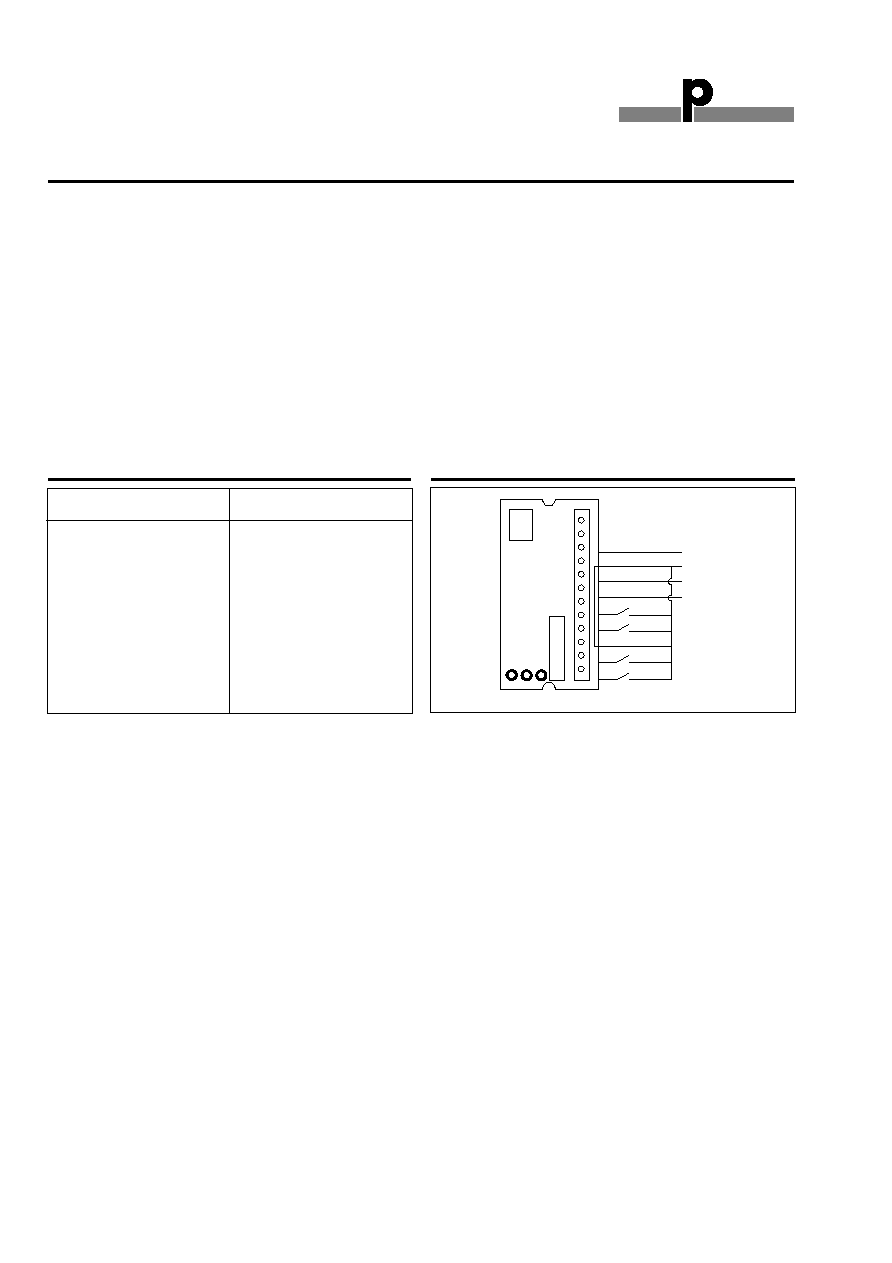
Pin Allocation
Terminal
Dup
Gnd
Pow
DC+
I4
I3
GND
I2
I1
Input/Output
Dupline
Æ
Signal
GND
Supply In
DC Out
Input 4
Input 3
GND
Input 2
Input 1
Wiring Diagram
G 2110 4401 700
The module uses only 2 (when
Dupline
Æ
-supplied) or 3 wires
for the communication and
the DC supply, i.e. the "com-
mon" of the communication
signal is the same as the
"minus" of the supply. In order
to achieve the noise immunity
stated in the datasheet, the
DC-supply must be applied to
the system through the Master
Modules G 2196 000X 700,
G 3496 000X 700 or the
G 3485 0000 700. The Master
Module also contains the
functions of a channel genera-
tor and an RS 485 communi-
cation interface (please refer
to the datasheet for
G 2196/G 3496 ... for details)
to the alarm controller.
Each signal input has its indi-
vidual address assigned to it
by means of the coding unit
GAP 1605 (please refer to the
datasheet for GAP 1605 for
details). The ON/OFF-signal
that is applied to the input is
associated to the address
given to that input. Any output
of an output-unit that is given
the identical address will now
follow that input-signal and
switch its output-signal ON or
OFF. This means that a signal
which is input at one location
may be output wherever
required and as many times as
required.
If the input-unit is connected
only to Dupline
Æ
(no 3-wire) it
still works, but DC out and the
line and power LED are dis-
abled. The built-in "Alarm
Armed" red LED is set by the
channel coded on I/O5. The
channel is typically set when
turning on the alarm surveil-
lance.
Supply
Line
Armed
G 2110 4401
Dup (Dupline S)
GND
Pow (Supply input)
DC+ (Supply output)
I4
I3
GND
I2
I1
CHANNEL
PROGRAM
PLUG
DUPLINE