Du line
Æ
Fieldbus
Installationbus
Specifications are subject to change without notice (29.04.03)
1
Dupline
Æ
is a registered trademark. A product of the CARLO GAVAZZI Group
∑ 2 push-button inputs
∑ 2 PNP-transistor outputs
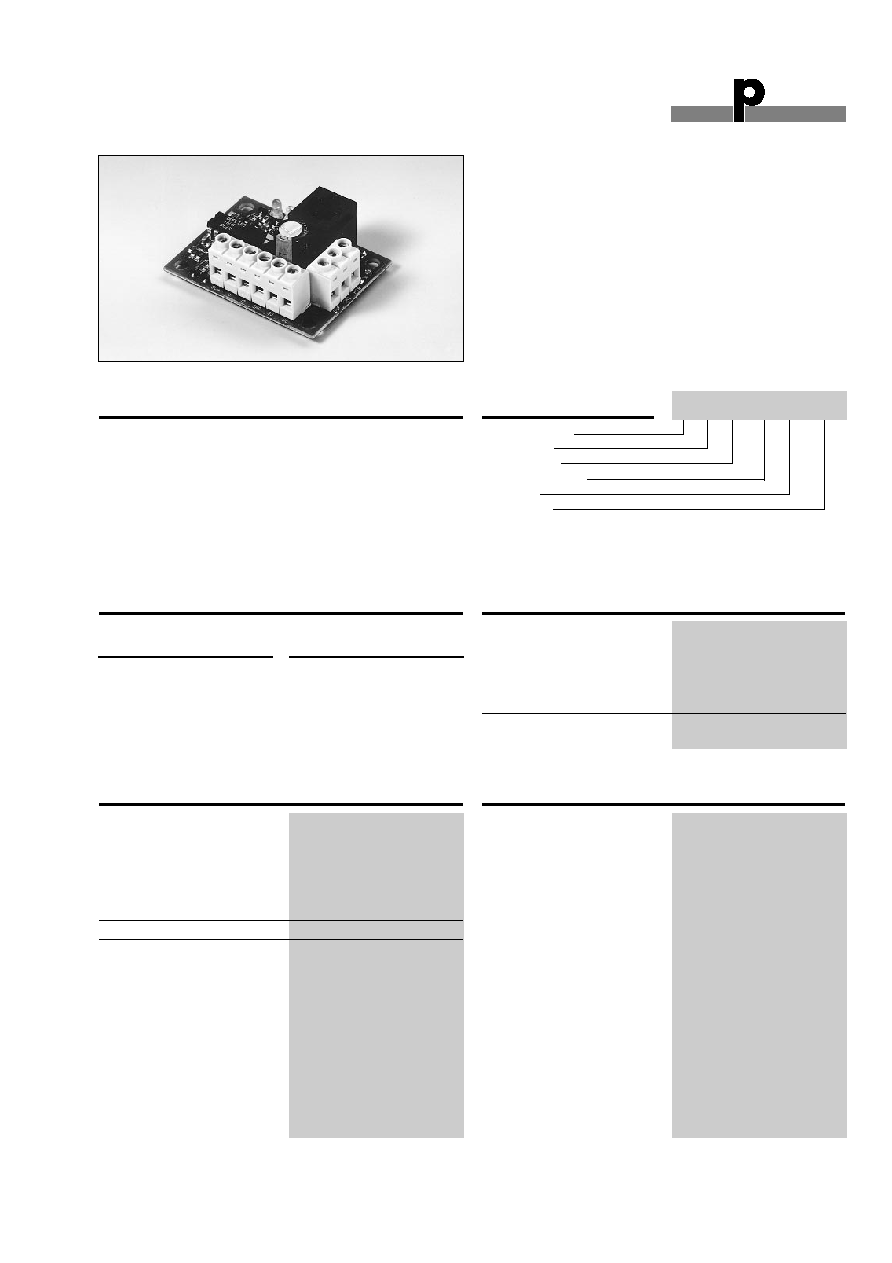
∑ Open printed circuit board
∑ Small size (54 x 40 mm)
∑ LED-indications for supply and Dupline
Æ
carrier
∑ DC-supply
∑ 3-wire system with Dupline
Æ
and supply of module
and output load through G 2196 0000 700
∑ Channel coding by GAP 1605
Product Description
Ordering Key
Direct interface to the I/O's
of elevator floor stations. The
input pulses are prolonged
to 0.5 s to ensure transfer of
fast push-button activations.
Due to the small size of the
module it can be integrated
into most push-button pan-
els. All modules in an eleva-
tor is connected to the same
3 wires for bus communica-
tion with the control system
and DC power supply for the
lamps. Installerfriendly mount-
ing, operation and mainte-
nance without requirements
for any special tools or pro-
gramming.
Type: Dupline
Æ
Open PCB
I/O-module
Number of I/Os
I/O-type
DC-supply
Type Selection
Supply
Ordering no.
PNP-outputs
10-30 VDC
G 2140 4421 700
G 2140 4421 700
Output Specifications
Input Specifications
Supply Specifications
I/O-Module for Elevators
Outputs
2 PNP-transistors
Output voltage drop
2.0 V
Current per output
200 mA
Short circuit protection
None
Built-in protective diodes
Yes
Off-state leakage current
200 µA
Response time
1 pulse train
(136 ms @ 128 channels)
Inputs
2 contacts or
NPN-transistor
Open loop voltage
8.0 VDC
Short circuit current
17 µA
Start peak current
20 mA
Contact resistance
100
Cable length
3 m
Response time
156 ms @ 128 channels
Input pulse prolongation
Typ. 0.5 s
Power supply
Overvoltage cat. III (IEC 60664)
Rated operational voltage (V
in
)
10-30 VDC (ripple included)
Ripple
3 V
Reverse polarity protection
Yes
Current consumption
30 mA
Power dissipation
1 W
Inrush current
1 A
Transient protection voltage
800 V
Dielectric voltage
Supply - Dupline
Æ
None
Supply - Inputs
None
Supply - Outputs
None
Type G 2140 4421 700

Du line
Æ
Fieldbus
Installationbus
2
Specifications are subject to change without notice (28.09.99)
Dupline
Æ
is a registered trademark. A product of the CARLO GAVAZZI Group
Mode of Operation
The I/O-units use three
wires for the communication
with all the other I/O-units of
an installation, for the sup-
ply of the I/O-units and for
the loads connected to the
outputs of the units. This
implies, that the "common"
of the communication signal
is identical to the "minus" of
the supply.
The DC-supply voltage must
connect to the system
through a G 2196 0000 700,
which also performs the chan-
nel generator function and the
RS485 communication link to
the elevator controller (please
refer to the data sheet for G
21960 000 700 for details)
Each I/O-unit has 2 inputs
(NPN/contact) and 2 PNP-
outputs. Every input and
output is given its individual
address with the coding unit
GAP 1605 (please refer to
the respective data sheet for
details). The ON/OFF-signal
that is applied to the input
of an I/O-unit is associated
to the address given to that
input. Any output of an I/O-
unit that is given the identi-
cal address will now follow
that input signal and switch
its output signal ON or OFF.
This means that a signal
which is input at one loca-
tion (for example as an out-
put from the lift controller)
may be output wherever
required and as many times
as required.
An input pulse stretcher is
used on every input to
assure that the changes of
input signals (even extreme-
ly short ones) are communi-
cated by the system.
The output status of all out-
puts of an I/O-unit may be
pre-defined for cases like
loss of power and loss of
communication. Please refer
to the paragraph "Output
status setting" of the data
sheet for the GAP 1605 to
change the default setting
(all outputs OFF).
Pin Allocation
Terminal
DUP
GND
POW
DC +
I 1
I 2
O 5
O 6
Input/Output
Dupline
Æ
signal
Dupline
Æ
+ supply GND
Supply IN
DC out
Input 1
Input 2
Output 1
Output 2
Wiring Diagram
DUPLINE
SUPPLY
CHANNEL
PROGRAM
PLUG
GND
O6
O5
POW
DUP
GND
I2
I1
DC+
G 2140 4421 700
Programming Information
GAP 1605
In/out 1
In/out 2
In/out 3
In/out 4
In/out 5
In/out 6
In/out 7
In/out 8
G 2140 4421
Input 1 (I1)
Input 2 (I2)
Not used
Not used
Output 1 (O5)
Output 2 (O6)
Not used
Not used
The table below shows the relation between the inputs/out-
puts of the G 2140 4421 and the In/Out-markings on the
GAP1605.
General Specifications
Power ON delay
Typ. 2 s
Indication for
Supply ON
LED, green
Dupline
Æ
carrier
LED, yellow
Environment
Operating temperature
-20∞ to +50∞C (-4∞ to +122∞F)
Storage temperature
-50∞ to +85∞C (-58∞ to +185∞F)
Humidity (non-condensing)
20 - 80%
Mechanical resistance
Shock
15 G (11 ms)
Vibration
2 G (6 to 55 Hz)
Dimensions
Open PCB 54 x 40 mm
4 pcs. of nylon PA6 snap
locks are included for mount-
ing the PCB in ¯ 4.8 holes
Weight
50 g