
Du line
Æ
Fieldbus
Installationbus
Specifications are subject to change without notice (10.05.2006)
1
Dupline
Æ
is a registered trademark. A product of the CARLO GAVAZZI Group
Product Description
Ordering Key
Type: Dupline
Æ
H4-housing
Receiver
No. of channels
Output type
Power supply
∑ 4 analog outputs
∑ Outputs individually configurable for 0-20 mA,
4-20 mA or 0-10 VDC
∑ Selectable resolution: 1/1999 or 1/255 of full scale
∑ Selectable dataformat : 8-bit, AnaLink or 3 1/2 digit BCD
∑ EMC immunity according to EN50082-2 (industrial envi-
ronment)
∑ DIN-rail mounting (EN 50022)
∑ Address-selection through rotary switches
∑ LED-indication for supply and Dupline
Æ
carrier
∑ LED-indication for invalid switch setting and faulty
received data
∑ Watchdog output for faulty received data
∑ H4 housing
Type Selection
Supply
Ordering no.
24 VAC
G 3439 6470 024
115 VAC
G 3439 6470 115
230 VAC
G 3439 7470 230
10-30 VDC
G 3439 6470 800
Output Specifications
Dupline
Æ
4 output universal
analog output module with
internal supply. The module
receives signals on a digital
format from Dupline
Æ
and
converts them to analog out-
puts. The output type can be
selected as 0-20 mA, 4-20
mA or 0-10 VDC for each
output individually making a
mix of analog output types on
the same module possible.
The transmission format on
Dupline
Æ
can be selected to
fit the output module into
existing installations, or simp-
ly to use the most suitable
combination of resolution,
signalling capacity and speed.
The formats are: 8-bit binary,
AnaLink and 3 1/2 digit BCD
(with or without multiplexing).
Universal Analog Output Module for
DIN-Signals
Type G 3439 6470
G 3439 6470 024
Outputs set to voltage
Outputs set to current
Signal
Signal output
DIN-voltage output
DIN-current output
Signal range
0-10 VDC
0-20 mA / 4-20 mA
Output load
100 k
0-450
Short circuit protection
Yes
Yes
Watchdog output
30 V
50 mA
Resolution
A/D
11 bits or 8 bits
11 bits or 8 bits
Transmission
1/1999 or 1/255
1/1999 or 1/255
Output settling time
0.5 sec.
0.5 sec
Inaccuracy (11-bit)
(ref. temp. 25∞C)
< 0.4% of full-scale
< 0.4% of full-scale
< 0.2% of reading
< 0.2% of reading
< 1 count
< 1 count
Temperature influence
(ref. temp. 25∞C)
< ±15 ppm/K of full-scale
< ±15 ppm/K of full-scale
< ±150 ppm/K of reading
< ±150 ppm/K of reading
Recommended cable length < 25 m
< 25 m
Dielectric voltage
Output - Dupline
Æ
250 VAC (rms)
250 VAC (rms)
Output - Watchdog output
2 kVAC (rms)
2 kVAC (rms)
Du line
Æ
Fieldbus
Installationbus
2
Specifications are subject to change without notice (30.04.03)
Dupline
Æ
is a registered trademark. A product of the CARLO GAVAZZI Group
Power supply AC-types
Overvoltage cat. lll (IEC 60664)
Operational voltage
through term. 21 & 22 230
230 VAC, -10/+15 % (IEC 60038)
115 115 VAC, -10/+15 % (IEC 60038)
024 24 VAC, -10/+15 %
Frequency
45 to 65 Hz
Power consumption
typ. 7 VA
Power dissipation
8 W
Rated impulse withstand
voltage
230
4 kV
115
2.5 kV
024 800 V
Dielectric Voltage
Supply - Dupline
Æ
4 kVAC (rms)
Supply - Signal output
4 kVAC (rms)
Supply - Watchdog output
4 kVAC (rms)
Power supply DC-types
Operational voltage
through term. 21 & 22 800
10,5 V - 30 VDC (Ripple incl.)
Ripple
< 3 V
Reverse polarity protection
Yes
Power consumption
< 4 W
Power dissipation
< 6 W
Rated impulse withstand
voltage
800 V
Dielectric Voltage
Supply - Dupline
Æ
500 VAC (rms)
Supply - Signal output
250 VAC (rms)
Supply - Watchdog output
2 kVAC (rms)
Power ON delay
2 s
Indication for
Supply ON
LED, green
Dupline
Æ
carrier
LED, yellow
Dupline
Æ
format error
LED, red
Illegal switch setting
LED, red - flashing
Environment
Degree of protection
IP 20
Pollution degree
3 (IEC 60664)
Operating temperature
0∞ to +50∞C (+32∞ to +122∞F)
Storage temperature
-20∞ to +85∞C (-4∞ to +185∞F)
Humidity (non-condensing)
20 to 80%
Mechanical resistance
Shock
15 G (11 ms)
Vibration
2 G (6 to 55 Hz)
Dimensions
Material
(see Technical information)
H4-Housing
Weight
300 g
CE-marking
Yes
G 3439 6470
Supply Specifications
General Specifications
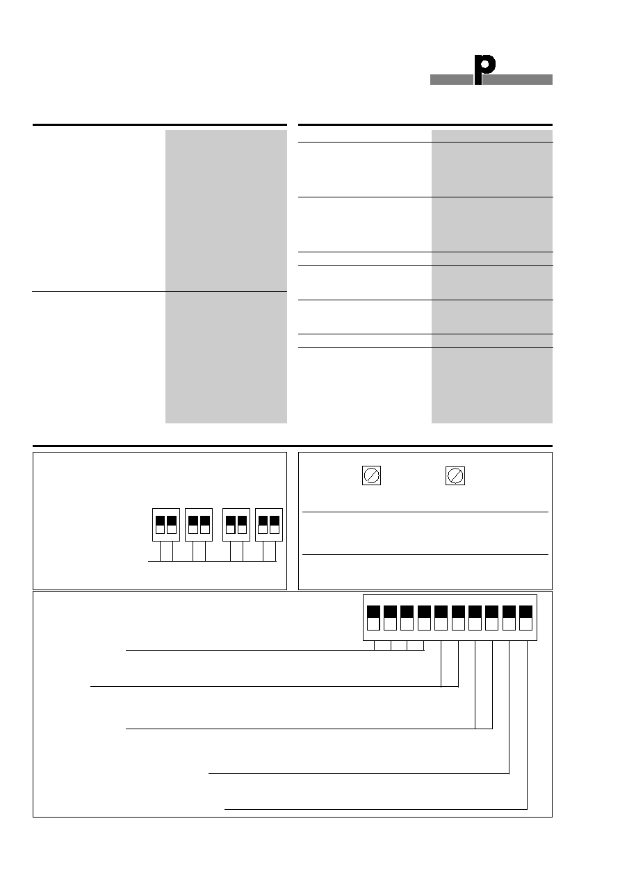
Switch Settings
Shunt-switches on system top
Current shunts on output 1-4:
ON/ON
= 0-10 V / (2-10 V)
OFF/OFF = 0-20 mA / 4-20 mA
Rotary switches in the front
Mode
3 1/2 digit:
Channel group-pair
Mux. address for output 1,
Ex. setting:
rest of the outputs (if enabled)
C or D = C-D
on the following addresses
8-bit:
Channel group
Same as 3 1/2 digit.
Ex. setting 5 (with 2 outputs
enabled) =
Output 1 on mux address 5
Output 2 on mux address 6
Analink:
Channel group
Channel no. for output 1, rest of
the outputs (if enabled) on the
following channels.
Setting of 0+9-F is not valid.
A-P
0-F
2
1
ON
3
4
6
5
7
8
10
9
Function switches in the front
Offset on output 1-4
ON = 4-20 mA / (2-10 V)
OFF = 0-20 mA / 0-10 V
No. of enabled outputs
OFF ON
: 1
ON
OFF : 2
ON
ON
: 3
OFF OFF : 4
Mode (Format)
OFF OFF : Analink
OFF ON
: 8-bit binary
ON
OFF : 3 1/2 digit BCD
ON
ON
: Reserved for future use
Multiplex ON/OFF
(Only used in 3 1/2 digit BCD and 8-bit binary mode)
ON
= Data is multiplexed
OFF = Data to output 1 is received on the group (or grouppair) rotarysw. A-P is set to,
data from input 2, 3, 4 (if enabled) on the following groups (or grouppairs)
Maintain ON/OFF
ON
= Keep output in case of Dupline
Æ
(or format) error
OFF = Zero output in case of Dupline
Æ
(or format) error
2
1
ON
2
1
ON
2
1
ON
2
1
ON
Du line
Æ
Fieldbus
Installationbus
Specifications are subject to change without notice (10.05.2006)
3
Dupline
Æ
is a registered trademark. A product of the CARLO GAVAZZI Group
G 3439 6470
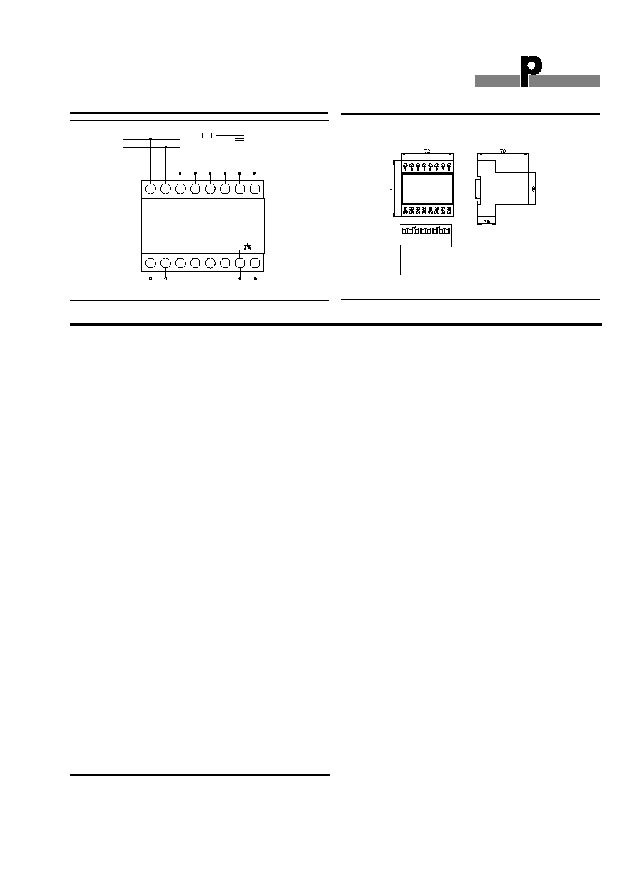
Wiring Diagram
Mode of Operation
The G34396470 is a univer-
sal analog module with 4
outputs. The outputs can be
configured individually for 0-
20 mA, 4-20 mA or 0-10 VDC
signals, making a mix of ana-
log output types on the same
module possible.The trans-
mission format is selectable
and supports all Dupline ana-
log protocols: 8-bit, AnaLink
and 3 1/2 digit BCD. The
module can be used in nor-
mal or multiplexed mode.
Address coding is done by
means of rotary switches and
the output and protocol
selection is done by means
of DIP-switches, so the GAP
1605 Programmer is not
required.
With reference to the dia-
gram on the previous page,
the setting of the module
should be performed in the
following way:
Select current or voltage sig-
nal for each output by means
of the 4 double-DIP-switch-
es on the top of the module.
If 4-20 mA is desired for an
output select off-set ON for
the corresponding switch on
the front of the module. The
module only outputs signals
according to the selected
number of enabled outputs
on switches 5 and 6.
Address allocation for the
Analink protocol:
If all four outputs are
enabled, the module will use
four Dupline
Æ
channels in
consecutive order, starting
from the address set on the
two rotary switches on the
front of the unit.
Example: Setting of "D7"
means that output 1 receives
on Dupline
Æ
channel D7, out-
put 2 receives on D8, output
3 receives on E1 and output
4 receives on E2.
Address allocation for the
8-bit binary protocol:
If all four outputs are enabled
and non multiplexed mode is
selected (switch 9), the mo-
dule will use four Dupline
Æ
channel groups (32 channels)
in consecutive order, starting
from the group set on the
first rotary switch (A-P). The
second rotary switch (0-F) is
not used in this mode.
Example: Setting of "F" on
the first rotary switch means
that output 1 receives on
Dupline
Æ
group F, output 2
receives on G, output 3
receives on H and output 4
receives on I.
If multiplexed mode is select-
ed the module will use one
Dupline
Æ
channel group (8
channels). The first rotary
switch (A-P) is used to set
the group and the second
rotary switch (0-F) to set the
multiplex address to be used
by the first output, no. 1.
Example: Setting of "F" on
the first rotary switch and "0"
on the second, means that
output 1 receives on
Dupline
Æ
group F mux. adr. 0,
output 2 receives on F mux.
adr. 1, output 3 receives on F
mux. adr. 2 and output 4
receives on F mux. adr. 3.
Address allocation for the 3
1/2 digit BCD protocol:
If all four outputs are enabled
and non-multiplexed mode is
selected (switch 9) the mo-
dule will use four Dupline
Æ
channel group-pairs (64
channels) in consecutive
order. The first rotary switch
(A-P) is used to set the start
group pair. The second rotary
switch (0-F) has no function
in this mode.
Example: Setting of "C" or
"D" on the first rotary switch
means that output 1 receives
on Dupline
Æ
group-pair C-D,
output 2 receives on E-F,
output 3 receives on G-H
and output 4 receives on I-J.
If multiplexed mode is select-
ed the module will use one
Dupline
Æ
channel group-pair
(16 channels). The first rotary
switch (A-P) is used to set
the group-pair and the sec-
ond rotary switch (0-F) to set
the multiplex address to be
used by the first output, no.
1.
Example: Setting of "C" or
"D" on the first rotary switch
and "8" on the second,
means that output 1 receives
on Dupline
Æ
group-pair C-D
mux. adr. 8, output 2
receives on C-D mux. adr. 9,
output 3 receives on C-D
mux. adr. A and output 4
receives on C-D mux. adr. B.
Note
The selected protocol is valid
for all enabled outputs. The
module can not receive dif-
ferent protocols at the same
time.
Analog reveivers must not be
used in systems where chan-
nel generators with 2 or 3
sequences are installed.
Accessories
DIN Rail
FMD 411
For further information refer to "Accessories".
1
2
3
4
21
22
27
28
S
Supply
24
23
6
7
8
5
26
25
O1
O2 O3
Watchdog
output
+ -
7VA
2,5W
(+)
(-)
O4
GND
GND
Dimensions (mm)
H4-housing