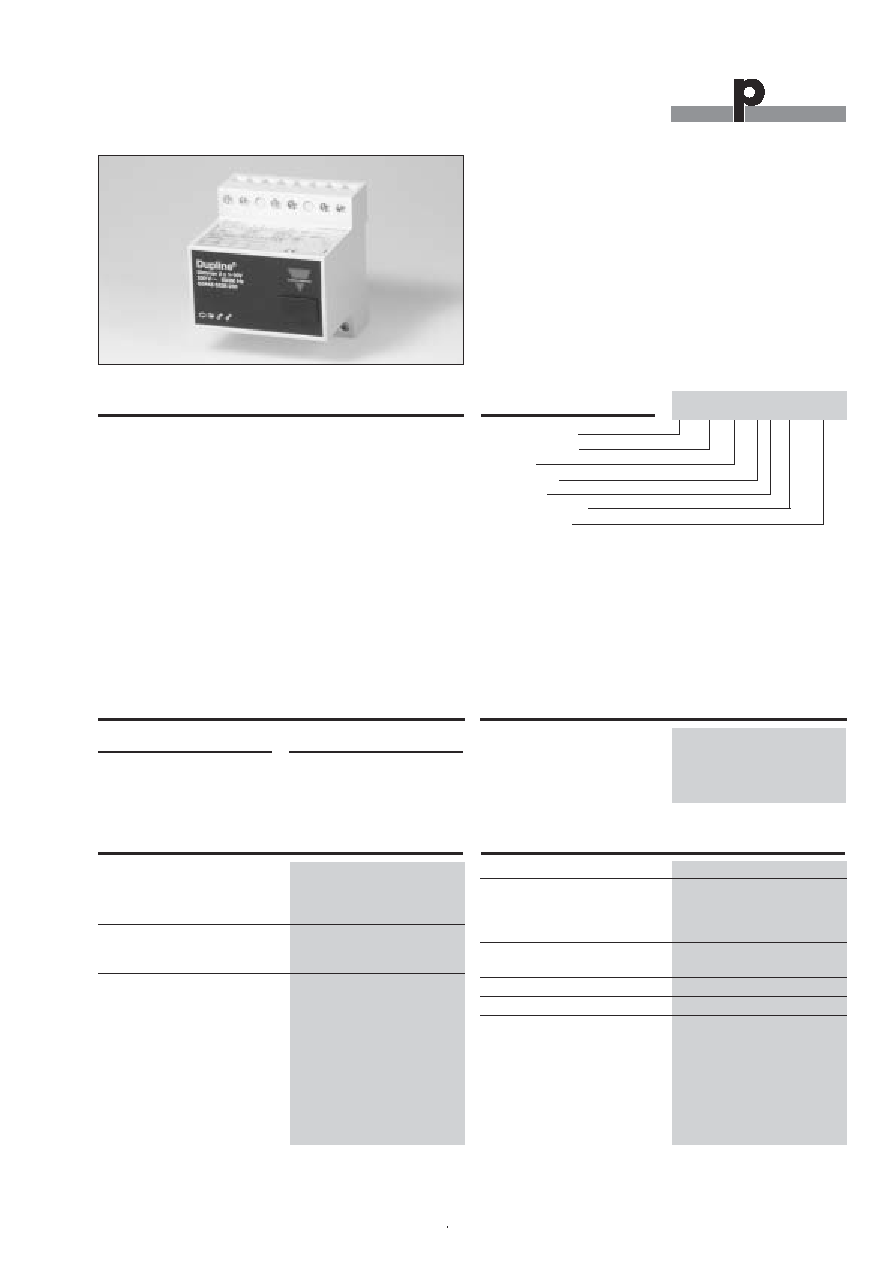
Type: Dupline
Æ
"H4"- Housing
Dimmer
8 Channels
2 outputs
1 to 10 V Analog
Power supply
Du line
Æ
Fieldbus
Installationbus
Specifications are subject to change without notice (28.02.03)
1
Dupline
Æ
is a registered trademark. A product of the CARLO GAVAZZI Group
Supply
Ordering no.
230 VAC
G 3448 5238 230
Ordering Key
Product Description
The G3448 5238 2-output
lighting scene dimmer is a
component of the Dupline
Installation System. It allows
different types of electronic
ballasts to be operated and
dimmed and enables up to 4
lighting arrangements (per
output) to be stored, which
can then be retrieved at any
time. In addition, it transmits
the status of the dimming out-
put for every individual output.
The dimmer setting which
was selected last is stored as
a "memory setting" in the
internal memory and is rese-
lected next time the lighting is
switched on via channel 1/5.
A power failure will erase the
memory setting. The bright-
ness of the lighting scenes is
preset at the factory in steps;
these settings cannot be
altered. By the aid of push-
button combinations or by
means of the test unit, the
lighting scenes can be
unlocked, modified and also
retrieved. The lighting is
switched on via a bulb-pre-
serving softstart facility.
∑ Switching and dimming of adjustable ballasts 1 to 10 V
∑ 8 control-channel receiver
∑ For DIN-rail mounting
∑ LED-indications for Dupline
Æ
carrier and outputs
∑ Bulb-conserving soft-start function
∑ Channel coding by GAP 1605
∑ 4 lighting scenes
∑ Transmits the status of the dimming outputs
Type Selection
Output Specifications
Ballast outputs
2
Dimming capacity
2 x 1 to 10 V
Max. load capacity
50 mA
Dimming speed
3.6 s (10% - 100%)
Relay outputs
2
Max. switching voltage
250 VAC
Load capacity
10 A
Response time
1 cycle:
272 ms @ 128 channels)
Supply Specifications
Power Supply
Rated operational voltage
230 VAC ±10%
Power consumption
2 VA
Power dissipation
Max. 4.5 W
Frequency
50/60 Hz
Dimmer, 2 outputs, 1 to 10 V
Type G 3448 5238
G 3448 5238 230
General Specifications
Power ON delay
1 s
Indication for
Power On
LED, Green
Dupline
Æ
carrier LED,
Yellow
Output On
LED, Red (one per output)
Environment
Operating temperature
0∞ to +50∞C/32∞ to +122∞F
Humidity (non-condensing) Max.
85%
Housing
H4-housing
Standards
IEC 60669, EN 55022/
EN 50081-1 and EN 55024/
EN 50082-1
Du line
Æ
Fieldbus
Installationbus
2
Specifications are subject to change without notice (28.02.03)
Dupline
Æ
is a registered trademark. A product of the CARLO GAVAZZI Group
Mode of Operation
Coding
With the GAP1605 programming unit, each switching channel
can be assigned any address between A1 and P8 via the mo-
dular socket on the front of the dimmer. The allocation of the
channels is as follows:
Functions which are not required should remain uncoded. The
coding of the dimmer can be carried out without either supply
voltage or Dupline signal. It is retained permanently, but may be
overwritten at any time. The Dimmer outputs are configured in
such a way at the factory that they will be switched off in the
event of a fault. This configuration, too, can be changed with
the GAP1605. Setting "1" results in switching on the lighting to
100% in case of a fault, while setting "0" switches off the Dim-
mer outputs (factory setting).
Putting into service
Commissioning may only be carried out by an authorized,
trained technician. Observe the connection diagram when
installing. All lines to be connected must be dead.
The following table shows the allocation of terminals:
Functions and programming
The dimmer is programmed with the GAP1605 programming
unit. Up to eight addresses can be programmed, 2 x 3 of which
(IN/OUT 1-3, 5-7 of the GAP1605) are dedicated to controlling
the dimmer itself (light level) - see the following table "Factory
Settings". The remaining two addresses (IN/OUT 4, 8 of the
GAP1605) are output signals on the bus and indicating if the
dimmers are activated. The addresses are selected in the con-
figuration software as push button channels.
The eight addresses (including two status signal addresses)
The light levels 3 and 4 can be programmed by combining 2
addresses.
( ) Factory settings
The shown values are factory settings and are consequently
protected against accidental resetting. Nevertheless, it is possi-
ble to disable the protection to change the default values. The
following steps 1-4 explain how the protection can be disabled,
the values changed, the protection reestablished and default
settings restored. The steps are explained with addresses for
Dimmer 1, but the same is valid for Dimmer 2.
Channel
Description
1
ON / OFF / Dimming
2
Lighting scene 1 (3)
3
Lighting scene 2 (4)
4
Dimmer 1 output status
5
ON / OFF / Dimming
6
Lighting scene 1 (3)
7
Lighting scene 2 (4)
8
Dimmer 2 output status
DIMMER 1
DIMMER 2
Terminal
Description
1
Dupline signal conductor + (D +)
2
Dupline signal conductor - (D -)
4
Dimmer 1, 1 to 10 V +
5
Dimmer 1, 1 to 10 V -
7
Dimmer 2, 1 to 10 V +
8
Dimmer 2, 1 to 10 V -
21
Line in
22
N-conductor
24
Dimmer 1 Relay, L
in
25
Dimmer 1 Relay, L
out
27
Dimmer 2 Relay, L
in
28
Dimmer 2 Relay, L
out
Address
Description
1
Dimmer up/down (long activation)
Turn on/Turn off (short activation)
2
Desired light level, see "Factory Settings"
3
Desired light level, see "Factory Settings"
4
Dimmer activated
5
Dimmer up/down (long activation)
Turn on/Turn off (short activation)
6
Desired light level, see "Factory Settings"
7
Desired light level, see "Factory Settings"
8
Dimmer activated
G 3448 5238
Channel combinations
Activation
(Dimmer1 / Dimmer2)
1 / 5
2 / 6
3 / 7
Short
Long
Dimming Up/Down
ON / OFF
10%..100%
Light. scene # 1 (40%) Store light. scene # 1
Light. scene # 2 (80%) Store light. scene # 2
Light. scene # 3 (20%) Store light. scene # 3
Light. scene # 4 (60%) Store light. scene # 4
Lock / Unlock
100%
(Locked)
Set light. scenes back
0% / OFF
to factory settings
Connections between the Dupline signal and to earth potential
will cause malfunctions and are not permissible. Attention
should be paid to the correct polarity of the supply voltage and
the Dupline signal. In order to meet the requirements for protec-
tive low voltage, VDE 0100, part 410, should be observed and
applied during installation.
Du line
Æ
Fieldbus
Installationbus
Specifications are subject to change without notice (28.02.03)
3
Dupline
Æ
is a registered trademark. A product of the CARLO GAVAZZI Group
1. Programming access (Unlock)
a) Activate address 2 and 3 for approx. 6 seconds.
b) When the light starts dimming fast up to 100%, down to
10% and back to actual value, the programming access
is open.
2. New light level
a) Open for the programming access according to 1. Pro
gramming access.
b) Use address 1 to set the required light level.
c) Activate, for approx. 3 seconds, the address to which the
chosen light level is to be allocated.
d) When the light starts dimming fast up to 100%, down to
10% and back to actual value, the new light level is
stored.
Undesirable changes of the programmed parameters can be
avoided by reestablishment of the programming protection ≠
see 3. Protection.
3. Protection (Lock)
a) Activate address 2 and 3 for approx. 6 seconds.
b) When the light starts dimming fast up to 100%, down to
10% and back to actual value, the programming access
is closed.
4. Restoring of factory settings
a) Activate address 1, 2 and 3 for approx. 9 seconds.
b) When the light starts dimming fast up to 100%, down to
10% and back to actual value, the factory settings are
restored.
When the factory settings are restored the programming pro
tection is not active.
LED indicators
Front-mounted LEDs indicate the status of the device:
LED
Description
GREEN
Supply ON
YELLOW
Dupline carrier:
"Bus OK"
OFF: Bus fault
ON: Bus is OK
RED
Dimmer 1:
Output 1
OFF: Dimmer output off
ON: Dimmer output on
RED
Dimmer 2:
Output 2
OFF: Dimmer output off
ON: Dimmer output on
Mode of Operation (cont.)
G 3448 5238
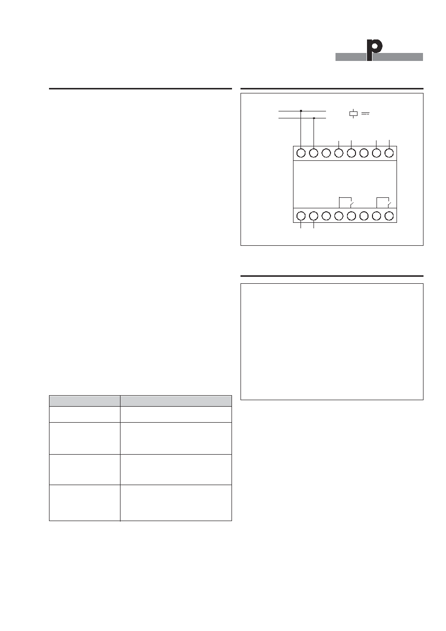
Wiring Diagram
1
2
3
4
21
22
27
28
D+
24
23
6
7
8
5
26
25
L
N
D-
Dupline
-
2
+
1
-
+
2 VA
~
Output
Dimmer 1
Output
Dimmer 2
Dimensions (mm)
H4-housing