Du line
Æ
Fieldbus
Installationbus
Specifications are subject to change without notice (30.04.03)
1
Dupline
Æ
is a registered trademark. A product of the CARLO GAVAZZI Group
Supply
Ordering no.
15 to 30 VDC
G 3485 0000 700
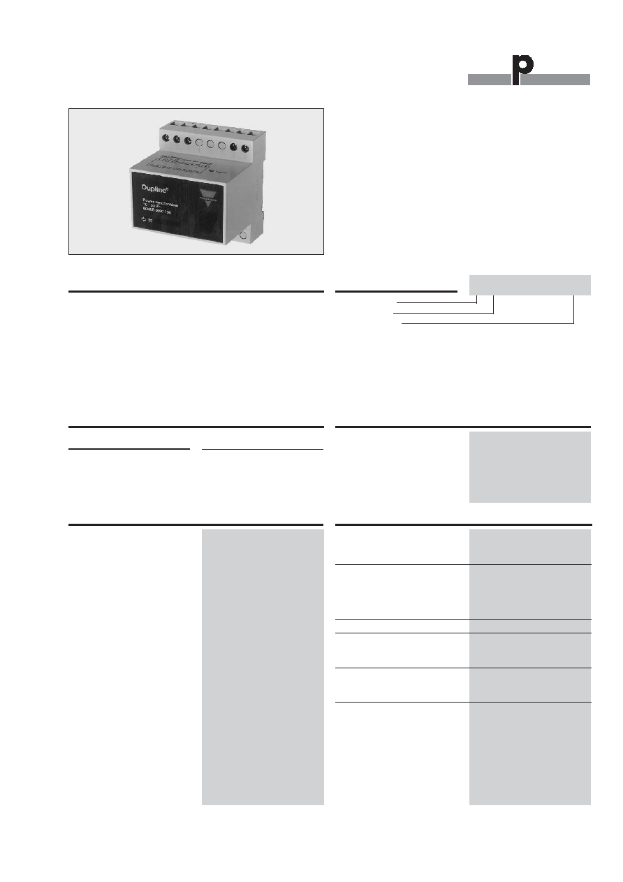
Type: Dupline
Æ
H4-Housing
Power supply
∑ For systems using a combined
communication-supply bus (3-wires)
∑ Input from a standard 15... 30 VDC power supply
∑ Coupling of transmission- and supply-common
∑ Output current 4 A max.
∑ H4-housing
Product Description
Type Selection
Supply Coupling Unit
Type G 3485 0000
Ordering Key
The supply coupling unit is
mainly used in those applica-
tions, where multiple
Dupline
Æ
modules of the type
G21...700 are to be supplied
through a DC-bus. Since
these modules use the same
wire for the common of the
transmission signal and the
"minus" of the DC-supply, the
G 3485 000 assures proper
coupling of the supply to
maximise the noise immunity
of the entire installation. To
supply a current
4 A (up to
25∞C) /
3 A (under 50∞C),
multiple coupling units may
be installed in parallel.
Output Specifications
Output
Output voltage V
BB
15 to 30 VDC (pulsating)
Output current
4 A (up to 25∞C)
3 A (under 50∞C
Short-circuit protection
None
Output voltage drop
1 VDC
Supply Specifications
Power supply
Installation cat. III (IEC 60664)
Operational voltage
through term. 7 (+) & 8
15 to 30 VDC (ripple included)
Ripple
3 V
Reverse polarity protection
Yes
Current consumption
30 mA
Power consumption
0,5 W
Inrush current
200 mA
Transient protection voltage
800 V
Insulation voltage
Supply - Dupline
Æ
None
Supply - output
None
General Specifications
Indication for
Dupline
Æ
carrier
LED, yellow
Supply
LED, green
Environment
Degree of protection
IP 20 B
Pollution degree
3 (IEC 60664)
Operating temperature
-20∞ to +50∞C (-4∞ to +122∞F)
Storage temperature
-50∞ to +85∞C (-58∞ to +185∞F)
Humidity (non-condensing)
20 to 80%
Mechanical resistance
Shock
15 G (11 ms)
Vibration
2 G (6 to 55 Hz)
Dimensions
Material
(See "Technical information")
H4-housing
Weight
200 g
G 3485 0000 700
Du line
Æ
Fieldbus
Installationbus
2
Specifications are subject to change without notice (22.03.2006)
Dupline
Æ
is a registered trademark. A product of the CARLO GAVAZZI Group
G 3485 0000
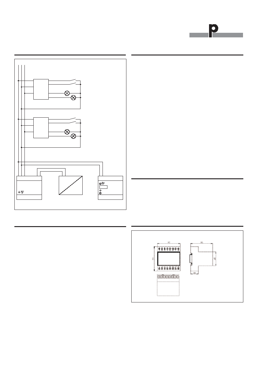
Wiring Diagram
Mode of Operation
The supply coupling unit was
designed for all those appli-
cations where DC-supplied
Dupline
Æ
modules of the type
G 21...700 are used. The
characteristic of these modu-
les is, that the common of the
transmission signal is identical
to the minus of the supply.
The catalogue states that
such modules shall not be
supplied by a DC-bus which
exceeds the distance of 3 m.
In the worst case this means
that an individual DC-supply
unit must be used for every
module. In some applications
this is impossible because
there is no power available at
site. The supply of such units
through a DC-bus can now be
done through the use of the
G 3485 0000.
The supply voltage at the
input terminals of the unit is
coupled to the output termi-
nals via a switching device
that is synchronised by the
Dupline
Æ
signal carrier. The
supply is decoupled from the
3-wire during the short peri-
ods of signal transmission
where a load current could
cause disturbances. The
maximum current per cou-
pling unit is
4 A (up to 25∞C)
/
3 A (under 50∞C). Multiple
coupling units may be
connected to the same sup-
ply in parallel if the maximum
current consumption of the
system (supply of Dupline
Æ
modules and supply of load)
exceeds the maximum output
for a single unit.
S: signal wire
S(Dupline
Æ
) I1
+
I2
GND
O1
O2
G2140 5520 700
S(Dupline
Æ
) I1
+
I2
GND
O1
O2
G2140 5520 700
1 2 3 4 5 6 7 8
21 22 23 24 25 26 27 28
=
~
Dupline
Æ
G3485 0000 700
D34900000
Accessories
DIN-rail
FMD 411
For further information refer to "Accessories".
Design Rules
Note the output voltage drop
of 1.0 V. This, together with
the output voltage drop of
G 2140 5507 00, should be
taken into consideration when
selecting the output voltage of
the standard DC-supply. Also,
the DC-supply must be able
to supply twice the total load
current, since the output volt-
age of G 3485 0000 700 is
pulsating.
There is a limit for the voltage
drop V
CW
in the common
wire.
V
CW
= R
CW
x I
TL
R
CW
: Resistance in the com-
mon wire
I
TL
= Total load current
If the load is distributed uni-
formly along the 3-wire, then
max. V
CW
is 3.5 V.
If the entire load is in the far
end from the G34850000700,
then the max. V
CW
is 2.0 V.
The above limitations can be
overcome by adding another
DC-supply with G34850000
700 along the line. Whenever
another pair (G3485000700
and DC-supply) is added the
two pairs will supply half the
load current running in half
the wire resistance and here-
by the V
CW
- limit is increased
by a factor of 4.
S
Dimensions (mm)
H4-housing