Du line
Æ
Fieldbus
Installationbus
Specifications are subject to change without notice (10.01.06)
1
Dupline
Æ
is a registered trademark. A product of the CARLO GAVAZZI Group
Supply
Ordering no.
No. of channels selectable
24 VAC
G 3490 0000 024
115 VAC
G 3490 0000 115
230 VAC
G 3490 0000 230
15 to 30 VDC
G 3490 0000 824
∑ Generates 8, 16, 24, 32, 40, 48, 56, 64, 96 or 128 channels
∑ Number of channels selectable by rotary switch
∑ Number of sequences (1 or 2) selectable
∑ Quartz-controlled oscillator
∑ Cable compensation
∑ DIN-rail mounting type (G3490) (EN 50022)
∑ LED-indication for supply and Dupline
Æ
carrier
∑ AC or DC power supply
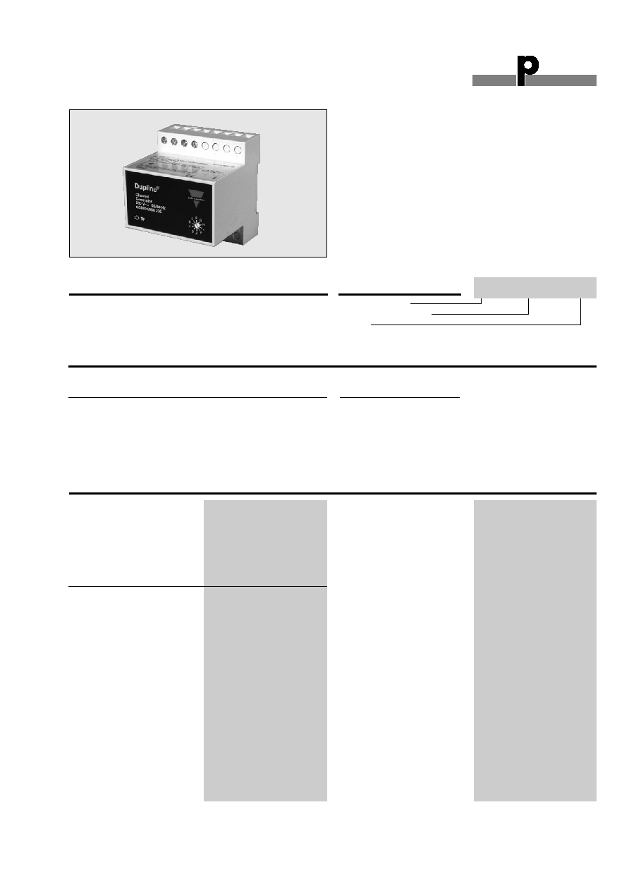
Product Description
Channel Generator
Types G 3490 0000
Type Selection
Input/Output Specifications
Inputs
1 contact
Function
2 sequences
Open loop voltage
12 VDC
Short-circuit current
1.25 mA
Contact resistance
100
Cable length
3 m
Insulation voltage
Input - Dupline
Æ
None
Outputs
Dupline
Æ
carrier
Number of outputs
1
Output voltage
8.2 VDC
Current
70 mA
Short-circuit protection
600 s
Output impedance
25
Type: Dupline
Æ
Channel generator
Supply
Ordering Key
G 34900000 230
Standard channel generators
for all Dupline
Æ
systems.
Number of channels select-
able by means of a rotary
switch.
Outputs (cont.)
Sequence time *
Time for 1 pulse train (± 1%):
Rotary
switch
No. of
position:
channels:
A
8
15.63 ms
B
16
23.44 ms
C
24
31.25 ms
D
32
39.06 ms
E
40
46.87 ms
F
48
54.68 ms
G
56
62.49 ms
H
64
70.31 ms
L
96
101.54 ms
P
128
132.80 ms
Distance to transmitters
100%
(refer to "Cable Selection")
* When using 2 sequences, the
sequence time will be 2 times
higher.
Du line
Æ
Fieldbus
Installationbus
2
Specifications are subject to change without notice (10.01.06)
Dupline
Æ
is a registered trademark. A product of the CARLO GAVAZZI Group
G 3490 0000
Supply Specifications
General Specifications
Power supply AC types
Overvoltage cat. III (IEC 60664)
Rated operational voltage
through term.: 21 & 22
230 230 VAC ± 10% (IEC 60038)
115 115 VAC ± 10% (IEC 60038)
024 24 VAC ± 10%
Frequency
45 to 65 Hz
Power dissipation
4 W
Voltage interruption
40 ms
Rated operational power
Typ. 2.5 VA
Rated impulse withstand
voltage
230 4 kV
115 2.5 kV
024 800 V
Dielectric voltage
Supply - Dupline
Æ
4 kVAC (rms)
Supply - Inputs
4 kVAC (rms)
Power supply DC types
Overvoltage cat. III (IEC 600664)
Rated operational voltage
through term.: 21 & 22
824 15 to 30 VDC (ripple included)
Power dissipation
3 W
Ripple
3 V
Reverse polarity protection
Yes
Current consumption
90 mA
Inrush current
1 A
Rated impulse withstand
voltage
800 V
Dielectric voltage
Supply - Dupline
Æ
None
Supply - Input
200 VAC (rms)
Power ON delay
3 s
Indication for
Supply ON
LED, green
Dupline
Æ
carrier
LED, yellow
Environment
Degree of protection
IP 20
Pollution degree
3 (IEC 60664)
Operating temperature
-20∞ to +50∞C (-4∞ to +122∞F)
Storage temperature
-50∞ to +85∞C (-58∞ to +185∞F)
Humidity (non-condensing)
20 to 80%
Mechanical resistance
Shock
15 G (11 ms)
Vibration
2 G (6 to 55 Hz)
Dimensions
Material
(see "Technical Information")
H4-housing
Weight
250 g
Mode of Operation
The channel generator gen-
erate a pulse trains and syn-
chronize the transmission
signal for an entire system of
Dupline
Æ
modules. At the
same time it supply non-
powered Dupline
Æ
transmit-
ters.
The selection of 1 or 2 se-
quences means that 1 or 2
consecutive signals of a
transmitter must show iden-
tical status until the channel
generator changes the duty
cycle for the respective
channel. This change of
duty cycle causes the
receivers to change their
status.
Note:
- Do not use 2 sequences if
analog modules or counters
are connected to the sy-
stem.
- The transmission distance
of a Dupline
Æ
network is
reduced by 33% when
using 2 sequences, com-
pared to the figures given
under "Cable Selection".
In Dupline
Æ
systems with digi-
tal transmitters and receivers
the use of 2 sequences is
only recommended in cases
of extremely long cabling in
high noise level environment.
Application of 2 sequences
results in absolutely correct
transmission but also in a
slow reaction time for the sys-
tem.
HF disturbance that is indu-
ced to the Dupline
Æ
may be
suppressed by interconnec-
tion of terminals 4 & 1 . For
inductive cables a separate
capacitor of less than 1 µF
may be mounted between ter-
minals 1 & 2. But in the majori-
ty of cases the cable appears
to be capacitive requiring no
additional capacitor.
Note:
It is highly
recommended to place the
channel generator in the
middle of a Dupline
Æ
system.
