Du line
Æ
Fieldbus
Installationbus
Specifications are subject to change without notice (11.01.2006)
1
Dupline
Æ
is a registered trademark. A product of the CARLO GAVAZZI Group
Du line
Æ
Fieldbus
Installationbus
Type: Dupline
Æ
Type no.
Supply
Input/Output Specifications
∑ Dupline
Æ
- private line modem
∑ Long distance connection of two Dupline
Æ
networks
∑ Approved according to EU standard TBR 15
∑ Watchdog output
∑ For mounting on DIN-rail (EN 50022)
∑ LED-indications for Supply, Dupline
Æ
and Fail
∑ AC Power Supply
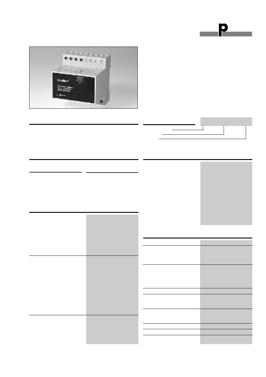
Product Description
Dupline
Æ
modem for bidirec-
tional signal transmission via
owned or rented telephone
cables or for installation of
Dupline
Æ
point to point con-
nections over distances
exceeding 10 km.
Ordering Key
Type Selection
Supply Specifications
Supply
Ordering no.
Dupline - Private line modem
24 VAC
G3491 0040 024
115 VAC
G3491 0040 115
230 VAC
G3491 0040 230
No code module required
Line interface
Line impedance
600 Ohm
Transmit level
< -9 dBm
Receive
Sensitivity
0 to -35 dBm
Transmission speed
300 Baud
Typical Response Time
128 channels
< 2.0 Sec
8 channels
< 0.5 Sec
Output
1 NPN transistor
Function
Watchdog,
operation as red LED
Output voltage
35 VDC
Output current
100 mA
Output Voltage drop
2 V
Off-state leakage current
100 µA
Short-circuit protection
None
Built-in protective diodes
None
Dielectric voltage
Output - Dupline
Æ
4 kVAC (rms)
Inductive loads
external noise suppression
required
Settings
Master/Slave:
Dip switch 1
Maintain
Dip switch 2
Power supply
Overvoltage cat. III (IEC 60664)
Rated operational voltage
through term. 21 & 22 230
230 VAC ± 15% (IEC 60038)
115
115 VAC ± 15% (IEC 60038)
024
24 VAC ± 15%
Frequency
45 to 65 Hz
Rated operational power
Typ. 3 W
Power dissipation
4 W
Rated operational withstand
voltage
230
4 kV
115
2.5 kV
024
800 V
Dielectric voltage
Supply - Dupline
Æ
4 kVAC (rms)
Private Line Modem
Type G 3491 0040
G 3491 0040 230
Power ON delay
< 1.5 Sec
Indication for
Supply on
LED, green
Dupline
Æ
carrier
LED, yellow
Communication Fail or No carrier LED, red
Environment
Degree of protection
IP 20
Pollution degree
3 (IEC 60664)
Operating temperature
0∞ to + 50∞C (-32∞ to +122∞F)
Storage temperatur
-20∞ to + 85∞C (-4∞ to +140∞F)
Humidity (non Condensing)
20 to 80% RH
Mechanical resistance
Stock
15 G (11 ms)
Vibration
2 G (6 to 55 Hz)
Dimensions
Material
(see Technical information)
H4-Housing
Weight
250 g
Approval
TRB 15
CE-marking
Yes
General Specifications

Du line
Æ
Fieldbus
Installationbus
2
Specifications are subject to change without notice (11.01.2006)
Dupline
Æ
is a registered trademark. A product of the CARLO GAVAZZI Group
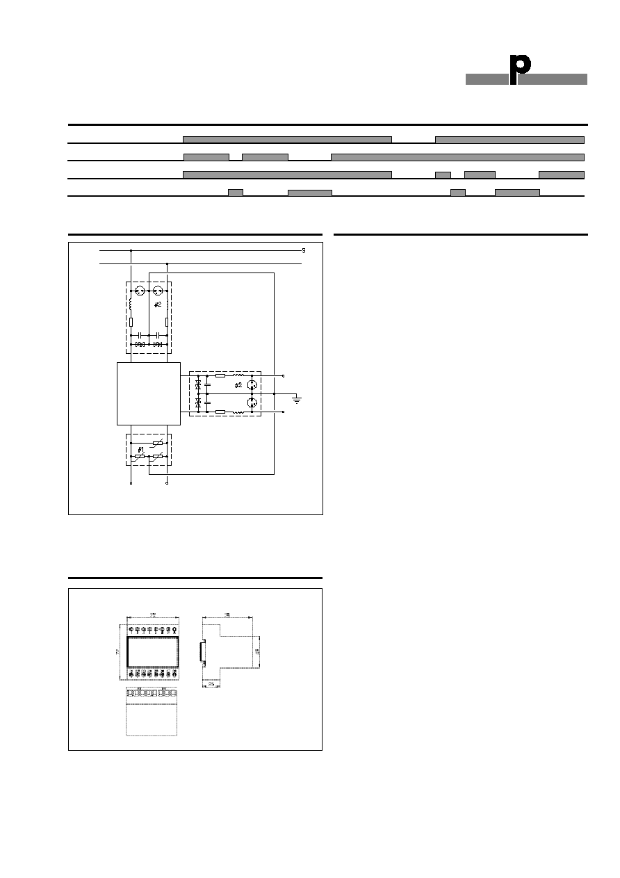
1
2
3
4
21
22
27
28
S
Watchdog NPN
AC Supply
Leased Line
24
23
6
7
8
5
26
25
+
-
0.1A
35V
S: signal wire
Wiring Diagram
G 3491 0040
Mode of Operation
The G 3491 0040 modems
connect 2 Dupline
Æ
systems
via owned or rented tele-
phone cables.
Two private line modems can
be used to establish long
distance connections between
two Dupline
Æ
-systems. A
G 3491 0040 must be
installed at each end of the
line and connected to the
owned or leased wire and to
the local Dupline
Æ
network. In
case of public telephone lines
without the need for perma-
nent connection, the D 9091
modem interface are used
together with commonly avail-
able modems.
G 3491 0040 converts all
Dupline
Æ
signals into standard
FSK (frequency shift keying)
tone signals. These signals
can be transmitted via the
telephone companies' stan-
dard lines/ amplifiers. In this
way Dupline
Æ
signals can be
exchanged over very long dis-
tances. In most countries the
telephone companies require
authorization prior to connec-
tion of the modem.
Each of the Dupline
Æ
instal-
lations to be connected must
have a channel generator
coded for the same number of
channels. Even so, one of the
two modems is to be set up
for master operation and the
other one for slave operation
(Dip switch 1).
When two Dupline
Æ
systems
are connected in this way, all
channels react as if it were
one Dupline
Æ
system. This
means that activation of e.g.
channel A1 in one system
automatically causes channel
A1 to be activated in the other
system. The modem contains
a watchdog output.
Any interruption of the Dupline
Æ
or private line leads to com-
munication breakdown. As
soon as the lines are reestab-
lished, communication starts
again automatically. The main-
tain input is used to define the
behaviour of the modem in
case of a communication break-
down. If maintain is selected
(Dip-Switch 2) the data of the
last valid transmission is kept
and the channels of the local
Dupline
Æ
are controlled
accordingly. This condition
remains until communication
is reestablished. If the main-
tain input is not activated, all
channels controlled from the
counterpart system are reset
in case of communication break-
down.
Only two modems (a master
and a slave) can be connect-
ed to a telephone line. Several
modems can, however, be
connected to one Dupline
Æ
system.
Note: It is recommended to
protect the modem by means
of external transient protec-
tion circuitry.
G 3491 0040 also transmit
analog values.
G 3491 0040 cannot com-
municate with FMX 1904.
2
1
ON
Attention Maintain
holds last received data
on the Dupline
Æ
chan-
nels, in case of commu-
nication failure.
Dip-Switch Settings
Sw Off
On
1 Master
Slave
2 Normal
Maintain
Du line
Æ
Fieldbus
Installationbus
Specifications are subject to change without notice (11.01.2006)
3
Dupline
Æ
is a registered trademark. A product of the CARLO GAVAZZI Group
Du line
Æ
Fieldbus
Installationbus
G 3491 0040
Watchdog output, Red LED
Private line
Dupline
Æ
carrier
Power supply
DIN-rail FMD
411
For further information refer to "Accessories".
Recommended types:
#1 DEHN type VED
#2 DEHN type ALE
1
21
22
28
26
2
Supply
Line
Accessories
Operation Diagram
Recommended Transient Protection
S: signal wire
Dimensions (mm)
H4-housing