
Du line
Æ
Fieldbus
Installationbus
Specifications are subject to change without notice (20.04.2006)
1
Dupline
Æ
is a registered trademark. A product of the CARLO GAVAZZI Group
Du line
Æ
Fieldbus
Installationbus
Type: Dupline
Æ
H4-Housing
Combined module
Interface type
DC supply
∑ Standard Optolink Protocol Slave
∑ Built-in normal Dupline
Æ
Channel Generator
∑ 128 I/O's and DC power supply on 3 wires
∑ RS232/RS422/RS485 port for interfacing to control
system
∑ Multidropping of up to 16 devices on RS485
∑ LED-indications for supply, Dupline
Æ
carrier and Com-
port TX
∑ Galvanically isolated Com-port supplied by internal
DC/DC converter
Product Description
Ordering Key
G 3496 0000 is designed as
a cost-effective solution for
interfacing Dupline
Æ
I/O's to
control systems. It performs
three functions: Dupline
Æ
channel generator, power
supply synchronization (en-
ables 3-wire system with
supply) and RS232/RS422/
RS485 interface.
Type Selection
Supply
PLC Interface type
Ordering no.
20-30 VDC
Optolink Standard protocol
G 3496 0000 700
G 3496 0000 700
Input/Output Specifications
Dupline
Æ
Master Module
Interface for Standard Optolink Protocol
Power output
Output voltage
20-30 VDC (pulsating)
Output current
< 3.0 A @ 50∫C
Short circuit protection
4 A quick acting fuse
Output voltage drop
< 1.0 V
Dupline
Æ
carrier
Output voltage
8.2 V (pulsating)
Current
< 60 mA
Short circuit protection
Yes
Scan time
128 channels
132.2 ms
64 channels
69.8 ms
Communication port
Standard
RS 232/RS 422/ RS 485
Split I/O / Normal mode
Normal mode
Connection
9 pole female SUB-D
Dielectric voltage
Com-port - Dupline
Æ
1 kVAC (rms)
Protocol
Optolink
Baud rate
19200
Data bits
8
Start bit
1
Stop bit
1
Parity
None
Flow-control
None
Type G 3496 0000
Input/Output Specifications (Cont.)
Pin assignment
2-wire RS 485
S/R Data line + (B)
Pin 3
S/R Data line - (A)
Pin 8
GND
Pin 5
4-wire RS 485/RS 422
R Data line + (B)
Pin 3
R Data line - (A)
Pin 8
S Data line + (B)
Pin 2
S Data line - (A)
Pin 7
Direction
Pin 4
(Connect to GND pin 5
when using 4-wire commu-
nication)
RS 232
TX
Pin 1
RX
Pin 9
GND
Pin 5
Supply Specifications
Power supply
Overvoltage cat. III (IEC 60664)
Operational voltage (V
in
)
20-30 VDC
Reverse polarity protection
None
Current consumption
< 150 mA + Power load
Power dissipation
< 5 W
Transient protection voltage
800 V
Dielectric voltage
Supply - Dupline
Æ
None
Supply - com-port
1 kVAC (rms)
* Note see wiring
diagrams for PC-
connection

Du line
Æ
Fieldbus
Installationbus
2
Specifications are subject to change without notice (20.04.2006)
Dupline
Æ
is a registered trademark. A product of the CARLO GAVAZZI Group
Mode of Operation
The Dupline
Æ
Master Module
is a Dupline
Æ
Channel
Generator with the function of
a slave. This means that the
128 Dupline
Æ
I/O's can be
read/controlled by a PC/PLC
or a Control board master from
many different suppliers. Up to
16 Dupline
Æ
Master Modules
can be connected to the same
network and operate together
with other modules using the
same protocol like operator
panels, MMI's frequency
inverters, I/O-modules etc.
When the Dupline
Æ
Master
Module has received a
telegram with output data for
Dupline
Æ
Receivers, it will
automatically respond with a
telegram with input data from
Dupline
Æ
Transmitters.
G 3496 0000
General Specifications
Power ON delay
2 s
Indication for
Com-port Tx
LED, red
Supply ON
LED, green
Dupline
Æ
carrier
LED, yellow
Environment
Pollution degree
3 (IEC 60664)
Operating temperature
0∞ to +50∞C (+32∞ to +122∞F)
Storage temperature
-50∞ to +85∞C (-58∞ to +185∞F)
Humidity (non-condensing)
20 to 80%
Mechanical resistance
Shock
15 G (11 ms)
Vibration
2 G (6 to 55 Hz)
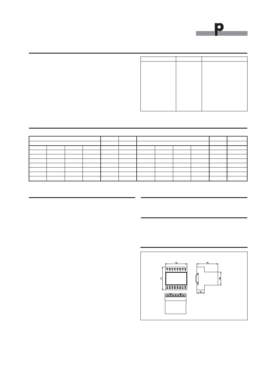
Dimensions
H4-Housing
Material
(see Technical information)
Weight
100 g
Dip-Switch Setting
Sw.1-4
On/Off:
Device no. 0-15 (all off = 0)
Sw.5 On:
64 Dupline
Æ
channels
Off:
128 Dupline
Æ
channels
Dupline
net 3
Dupline
net 2
Dupline
net 1
DMM slave No. 1
DMM slave No. 2
DMM slave No. 3
Multidrop Cable
Multidrop Cable
RS 485
Programmer (Master)
PC/PLC
RS 232
Converter
Wiring Diagrams
Dupline net
DMM slave
PC/PLC Master
RS 232/RS 422/RS 485
Multidrop
Peer to Peer
1
2
3
4
21
22
27
28
Supply in
20-30 V DC
24
23
6
7
8
5
26
25
+
-
Power out
GND
Dupline Signal
RS 232
RS 485
3W
Device no.
Sw1
Sw2
Sw3
Sw4
00
0
0
0
0
01
0
0
0
1
02
0
0
1
0
03
0
0
1
1
-
14
1
1
1
0
15
1
1
1
1
PC
G3496
0000
DP9
DP9
Pin
2
Pin
1
Pin
3
Pin
9
Pin
5
Pin
5
Cable wiring between PC and DMM
Du line
Æ
Fieldbus
Installationbus
Specifications are subject to change without notice (20.04.2006)
3
Dupline
Æ
is a registered trademark. A product of the CARLO GAVAZZI Group
Du line
Æ
Fieldbus
Installationbus
Telegram Structure
Memory Mapping
Channel Status
Hex
ASCII
Channel Status
Hex
ASCII
Ch. 1 - Ch. 4 / Ch. 5 - Ch. 8
Ch. 1 - Ch. 4 / Ch. 5 - Ch. 8
0
0
0
0
0
@
1
0
0
0
8
H
0
0
0
1
1
A
1
0
0
1
9
I
0
0
1
0
2
B
1
0
1
0
A
J
0
0
1
1
3
C
1
0
1
1
B
K
0
1
0
0
4
D
1
1
0
0
C
L
0
1
0
1
5
E
1
1
0
1
D
M
0
1
1
0
6
F
1
1
1
0
E
N
0
1
1
1
7
G
1
1
1
1
F
O
ASCII Transformation for a Group of 4 Dupline
Æ
Channels
Installation Hints
No TX-LED
Checksum Error
The Checksum is being cal
culated in a wrong way.
Order/download the document:
Telegram structure for DMM
G34960000 from our Home-
page: www.dupline.com
Wrong telegram structure
See "Telegram Structure"
Hardware fault
Check the wiring. Try to
send the telegram-example
mentioned in "Telegram
Structure".
No Dupline
Æ
Carrier-LED
Short circuit
Short circuit between the
two Dupline
Æ
wires.
Request response
Check the Turnaround delay
in the Status byte.
Accessories
Document
Telegram Structure for DMM G34960000
Additional Information
Scope of supply
1 x Master Module
G3496 0000 700
G 3496 0000
Field Name
Example
Description
Start
s
Start
Destination Address
@M
Addressed to DMM no. 13
No. og Data words
@H
8 data words (Group A - H)
Status
@A
Turnaround delay = 1ms
Source Address
A@
PC / PLC is always 10 Hex
Data word# 1
NB
Set A1,A2,A3,A4
Clear A4,A5,A6,A8
Data word# 2 - 8
@@,@@,...@@
Clear Group B - H
Checksum
OH
End
e
END
All telegrams are built up as
shown in schedule - no matter
if they are sent from the
PC/PLC/ Controlboard to the
DMM or they are returned by
the DMM.
The communication is execut-
ed by using telegrams that
start with the ASCII-character
"s" and end with the ASCII-
character "e". All information
transmitted between these
two characters is compressed
to achieve short telegrams
with a high data throughput.
By using this compression, the
signal status of the 8 channels
within a Dupline
Æ
address
group are transmitted as only
two ASCII-characters. This is
done by converting the lower
4-Bit and the upper 4-Bit of a
Data byte into hexadecimal
numbers and the subsequent
transformation of these num-
bers into ASCII-characters.
Dimensions (mm)
H4-housing