Du line
Æ
Fieldbus
Installationbus
Specifications are subject to change without notice (05.05.03)
1
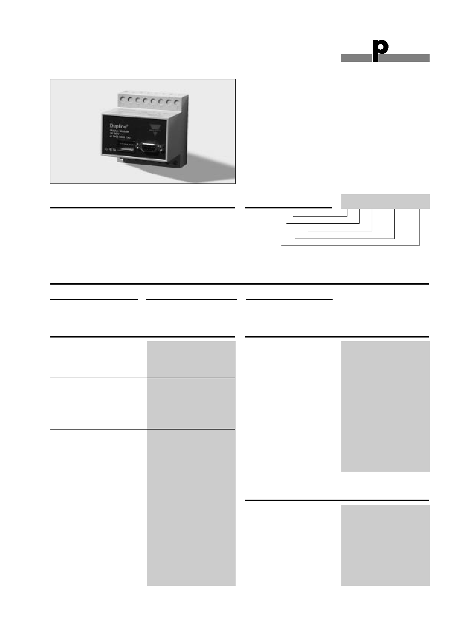
Dupline
Æ
is a registered trademark. A product of the CARLO GAVAZZI Group
Type: Dupline
Æ
H4-Housing
Combined module
Interface type
DC supply
∑ Lucky Goldstar master
∑ Plug and play: Automatic communication with specific
PLC/Controllers
∑ Built-in normal Dupline
Æ
Channel Generator
∑ 128 I/O's and DC power supply on 3 wires
∑ RS232/RS422/RS485 port for interfacing to control
system
∑ Split-I/O mode selectable (128 inputs and 128 outputs)
∑ LED-indications for supply, Dupline
Æ
carrier and Com-
port Tx
∑ Galvanically isolated Com-port supplied by internal
DC/DC converter
Product Description
Ordering Key
G 3496 0001 is designed as
a cost-effective Plug & Play
solution for interfacing
Dupline
Æ
I/O's to a Lucky
Goldstar PLC. It performs
three functions: Dupline
Æ
channel generator, power
supply synchronization (en-
ables 3-wire system with
supply) and RS232/RS422/
RS485 interface.
Type Selection
Supply
PLC Interface type
Ordering no.
20-30 VDC
Lucky Goldstar K-serie
G 3496 0001 700
G 3496 0001 700
Input/Output Specifications
Dupline
Æ
Plug & Play Master Module
Interface for Lucky Goldstar PLC
Power output
Output voltage
20-30 VDC (pulsating)
Output current
< 3.0 A @ 50∫C
Short circuit protection
4 A quick acting fuse
Output voltage drop
< 1.0 V
Dupline
Æ
carrier
Output voltage
8.2 V (pulsating)
Current
< 60 mA
Short circuit protection
Yes
Scan time
128 channels
132.2 ms
64 channels
69.8 ms
Communication port
Standard
RS232/RS422/RS485
Split I/O mode
Yes, selectable
Normal Dupline mode
Yes, selectable
Connection
9 pole female Sub-D
Dielectric voltage
Com-port Dupline
Æ
1 kVAC (rms)
Protocol
LG Serial Communication
Standard
Baud rate
19200
Data bits
8
Start bit
1
Stop bit
1
Parity
None
Flow-control
None
Type G 3496 0001
Input/Output Specifications (Cont.)
Pin assignment
2-wire RS 485
S/R Data line + (B)
Pin 3
S/R Data line - (A)
Pin 8
GND
Pin 5
4-wire RS 485/RS 422
R Data line + (B)
Pin 3
R Data line - (A)
Pin 8
S Data line + (B)
Pin 2
S Data line - (A)
Pin 7
Direction
Pin 4
(Connect to GND pin 5
when using 4-wire commu-
nication)
RS 232
TX
Pin 1
RX
Pin 9
GND
Pin 5
Supply Specifications
Power supply
Overvoltage cat. III (IEC 60664)
Operational voltage (V
in
)
20-30 VDC
Reverse polarity protection
None
Current consumption
< 150 mA + Power load
Power dissipation
< 5 W
Transient protection voltage
800 V
Dielectric voltage
Supply - Dupline
Æ
None
Supply - com-port
1 kVAC (rms)

Power ON delay
2 s
Indication for
Com-port Tx
LED, red
Supply ON
LED, green
Dupline
Æ
carrier
LED, yellow
Environment
Pollution degree
3 (IEC 60664)
Operating temperature
0∞ to +50∞C (+32∞ to +122∞F)
Storage temperature
-50∞ to +85∞C (-58∞ to +185∞F)
Du line
Æ
Fieldbus
Installationbus
2
Specifications are subject to change without notice (30.08.00)
Dupline
Æ
is a registered trademark. A product of the CARLO GAVAZZI Group
Mode of Operation
The Dupline
Æ
Master Module
(DMM) controls a 3-wire bus
with signal, DC-power and
common GND. The DMM is
connected to a standard DC-
supply, which it synchronizes
with the Dupline
Æ
carrier signal
before it is output to supply.
The synchronization is neces-
sary in order to enable the
Dupline
Æ
and DC-supply to
share the GND-wire.
The Dupline
Æ
Master Module is
a Dupline
Æ
Channel Generator
with the function of a master.
This means that the 128
Dupline
Æ
I/O's will be read/writ-
ten by the DMM and then sent
to the PLC.
The DMM can run in two dif-
ferent modes ≠ Normal mode
and split I/O mode. In Normal
mode, Dupline
Æ
operates as a
peer-to-peer system, where
the channel generator auto-
matically establishes a con-
nection between Dupline
Æ
inputs and Dupline
Æ
outputs
which are coded to the same
Dupline
Æ
address. If e.g. an
input coded for B5 is activat-
ed, the output(s) coded for B5
will also be activated.
Consequently, a Dupline
Æ
-out-
put can either be activated
through the output-data
received on DMM or by an
active Dupline
Æ
input coded
for the same Dupline
Æ
-
address. In "Split I/O" mode,
the channel generator treats
the Dupline
Æ
inputs and
Dupline
Æ
outputs indepen-
dently. If e.g. an input coded
for B5 is activated, the DMM
will make the information avail-
able for the PLC (like in normal
mode), but it will not automati-
cally activate the Dupline
Æ
out-
put(s) coded to B5. The
Dupline
Æ
outputs are con-
trolled exclusively through the
output data received from the
PLC. In this mode, up to 128
Dupline
Æ
inputs and 128
Dupline
Æ
outputs are available,
since an input and an output
coded to the same Dupline
Æ
address can operate indepen-
dently.
G 3496 0001
General Specifications
Humidity (non-condensing)
20 to 80%
Mechanical resistance
Shock
15 G (11 ms)
Vibration
2 G (6 to 55 Hz)
Dimensions
H4-Housing
Material
(see Technical information)
Weight
100 g
Dip-Switch Setting
Sw.4
On:
Split I/O Channel Generator Mode
(See "Mode of Operation")
Off:
Normal Dupline
Æ
Monostable Channel
Generator Mode
Sw.5
On:
64 Dupline
Æ
channels
Off:
128 Dupline
Æ
channels
Installation Hints
No TX-LED
Hardware fault
Check the wiring.
No Dupline
Æ
Carrier-LED
Short circuit
Short circuit between the
two Dupline
Æ
wires.
Pin Assignment
1
9
8
7
6
5
4
3
2
Only for G 2196 0001
Wiring Diagram
1
2
3
4
21
22
27
28
Supply in
20-30 V DC
24
23
6
7
8
5
26
25
+
-
Power out
GND
Dupline Signal
RS 232
RS 485
3W

Du line
Æ
Fieldbus
Installationbus
Specifications are subject to change without notice (30.08.00)
3
Dupline
Æ
is a registered trademark. A product of the CARLO GAVAZZI Group
Memory Mapping
Dupline
Æ
Lucky Goldstar
Dupline
Æ
Lucky Goldstar
Channel
Channel
Read
Write
Read
Write
A1
M000
M080
E1
M020
M100
A2
M001
M081
F1
M028
M108
A3
M002
M082
G1
M030
M110
A4
M003
M083
H1
M038
M118
A5
M004
M084
I1
M040
M120
A6
M005
M085
J1
M048
M128
A7
M006
M086
K1
M050
M130
A8
M007
M087
L1
M058
M138
B1
M008
M088
M1
M060
M140
B8
M00F
M08F
N1
M068
M148
C1
M010
M090
O1
M070
M150
D1
M018
M098
P1
M078
M158
Table of the memory mapping
Accessories
Cable for Communication port
RS485-CAB
Additional Information
Scope of supply
1 x Master Module
G3496 0001 700
G 3496 0001