
Du line
Æ
Fieldbus
Installationbus
Specifications are subject to change without notice (05.05.03)
1
Dupline
Æ
is a registered trademark. A product of the CARLO GAVAZZI Group
Type: Dupline
Æ
H4-Housing
Combined module
Interface type
DC supply
∑ Allen Bradley Master
∑ Plug and play: Automatic communication with specific
PLC/Controllers
∑ Built-in normal Dupline
Æ
Channel Generator
∑ 128 I/O's and DC power supply on 3 wires
∑ RS232 port for interfacing to control system
∑ Split-I/O mode selectable (128 inputs and 128 outputs)
∑ LED-indications for supply, Dupline carrier and Com-
port TX
∑ Galvanically isolated Com-port supplied by internal
DC/DC converter
Product Description
Ordering Key
G 3495 0006 is designed as a
cost-effective solution for
interfacing Dupline
Æ
I/O's to
Allen Bradley PLCs ≠ the SLC
500 and Micrologix families.
It performs three functions:
Dupline
Æ
channel generator,
power supply synchroniza-
tion (enables 3-wire system
with supply) and RS232 inter-
face.
Type Selection
Supply
PLC Interface Conformance
Ordering no.
20-30 VDC
MicroLogix 1000, 1200 and 1500. SLC5-03, SLC5-04 and SLC5-05.
G 3496 0006 700
G 3496 0006 700
Input/Output Specifications
Dupline Plug & Play Master Module
Interface for Allen Bradley PLC
Power Output
Output voltage
20-30 VDC (pulsating)
Output current
< 3.0 A @ 50∞C
Short circuit protection
4 A quick acting fuse
Output voltage drop
< 1.0 V
Dupline
Æ
carrier
Output voltage
8.2 V (pulsating)
Current
< 60 mA
Short circuit protection
Yes
Scan time
128 channels
132.2 ms
64 channels
69.8 ms
Communication Port
Standard
RS232
Connection
9 pole female Sub-D
Dielectric voltage
Com-port-Dupline
Æ
1 kVAC (rms)
Protocol
DF1
Channel Configuration in PLC
Driver
DF1 Full Duplex
Source ID
1
Baud rate
9600
Data bits
8
Start bit
-
Stop bit
1
Parity
None
Flow-control
None
Error detection
CRC or BCC
Pin assignment
RS232
TX
1
Rx
9
GND
5
Type G 3496 0006
Supply Specifications
Power supply
Overvoltage cat. III (IEC 60664)
Operational voltage (V
in
)
20-30 VDC
Reverse polarity protection
None
Current consumption
< 150 mA + Power load
Power consumption
< 5 W
Transient protection voltage
800 V
Dielectric voltage
Supply ≠ Dupline
Æ
None
Supply ≠ Com-port
1 kVAC (rms)
Power ON delay
2 s
Indication for
Com-port TX
LED, red
Supply ON
LED, green
Dupline
Æ
carrier
LED, yellow
Environment
Pollution degree
2 (IEC 60664)
Operating temperature
0∞ to +50∞C (+32∞ to +122∞F)
Storage temperature
-50∞ to +85∞C (-58∞ to +185∞F)
Humidity (non-condensing)
20 to 80%
Mechanical resistance
Shock
15 G (11 ms)
Vibration
2 G (6 to 55 Hz)
Dimensions
H4-Housing
Material
(See Technical Information)
Weight
100 g
General Specifications

Du line
Æ
Fieldbus
Installationbus
2
Specifications are subject to change without notice (29.08.00)
Dupline
Æ
is a registered trademark. A product of the CARLO GAVAZZI Group
Mode of Operation
The Dupline
Æ
Master Module
(DMM) controls a 3-wire bus
with signal, DC-power and
common GND. The DMM is
connected to a standard DC-
supply, which it synchronizes
with the Dupline
Æ
carrier signal
before it is output to supply.
The synchronization is neces-
sary in order to enable the
Dupline
Æ
and DC-supply to
share the GND-wire.
The Dupline
Æ
Master Module is
a Dupline
Æ
Channel Generator
with the function of a master.
This means that the 128
Dupline
Æ
I/0's will be read/writ-
ten by the DMM and then sent
to the PLC.
The DMM can run in two dif-
ferent modes ≠ Normal mode
and split I/O mode. In Normal
mode, Dupline
Æ
operates as a
peer-to-peer system, where
the channel generator auto-
matically establishes a con-
nection between Dupline
Æ
inputs and Dupline
Æ
outputs
which are coded to the same
Dupline
Æ
address. If e.g. an
input coded for B5 is activat-
ed, the output(s) coded for B5
will also be activated.
Consequently, a Dupline
Æ
-out-
put can either be activated
through the output-data
received on DMM or by an
active Dupline
Æ
input coded
for the same Dupline
Æ
-
address. In "Split I/O" mode,
the channel generator treats
the Dupline
Æ
inputs and
Dupline
Æ
outputs indepen-
dently. If e.g. an input coded
for B5 is activated, the DMM
will make the information avail-
able for the PLC (like in normal
mode), but it will not automati-
cally activate the Dupline
Æ
out-
put(s) coded to B5. The
Dupline
Æ
outputs are con-
trolled exclusively through the
output data received from the
PLC. In this mode, up to 128
Dupline
Æ
inputs and 128
Dupline
Æ
outputs are available,
since an input and an output
coded to the same Dupline
Æ
address can operate indepen-
dently.
G 3496 0006
Dip-Switch Setting
Sw.2
On:
Checksum CRC
Off:
Checksum BCC
Sw.4
On:
Split I/O Channel Generator Mode
Off:
Normal Dupline
Æ
Monostable Channel
Generator Mode
Sw.5 On:
64 Dupline
Æ
channels
Off:
128 Dupline
Æ
channels
Sw.6
On:
Maintain data to Dupline
Æ
receivers in
case of communication failure
Off:
Clear data to Dupline
Æ
receivers in case of
communication failure after 75 Dupline
Æ
scans
Memory Mapping
Configuration of data file in RSLogix 500 Programming
DATA FILE
MicroLogix & SLC
Type: 1000
Type: Other
File 7
9
Type
N (Integer)
N (Integer)
Elements
16*
16*
Dupline
Æ
MicroLogix & SLC
Dupline
Æ
MicroLogix & SLC
Channel Channel
Read
Write
Read
Write
A1
N9: 0/0
N9: 8/0
E1
N9: 2/0
N9: 10/0
A2
N9: 0/1
N9: 8/1
F1
N9: 2/8
N9: 10/8
A3
N9: 0/2
N9: 8/2
G1
N9: 3/0
N9: 11/0
A4
N9: 0/3
N9: 8/3
H1
N9: 3/8
N9: 11/8
A5
N9: 0/4
N9: 8/4
I1
N9: 4/0
N9: 12/0
A6
N9: 0/5
N9: 8/5
J1
N9: 4/8
N9: 12/8
A7
N9: 0/6
N9: 8/6
K1
N9: 5/0
N9: 13/0
A8
N9: 0/7
N9: 8/7
L1
N9: 5/8
N9: 13/8
B1
N9: 0/8
N9: 8/8
M1
N9: 6/0
N9: 14/0
B8
N9: 0/15
N9: 8/15
N1
N9: 6/8
N9: 14/8
C1
N9: 1/0
N9: 9/0
O1
N9: 7/0
N9: 15/0
D1
N9: 1/8
N9: 9/8
P1
N9: 7/8
N9: 15/8
Table of the memory mapping to the PLC
(Except MicroLogix 1000)
*Registers 0-7: Dupline
Æ
Input Channels A1 to P8.
Registers 8-15: Dupline
Æ
Output Channels A1 to P8.
Dupline
Æ
MicroLogix 1000
Dupline
Æ
MicroLogix 1000
Channel
Channel
Read
Write
Read
Write
A1
N7: 0/0
N7: 8/0
E1
N7: 2/0
N7: 10/0
A2
N7: 0/1
N7: 8/1
F1
N7: 2/8
N7: 10/8
A3
N7: 0/2
N7: 8/2
G1
N7: 3/0
N7: 11/0
A4
N7: 0/3
N7: 8/3
H1
N7: 3/8
N7: 11/8
A5
N7: 0/4
N7: 8/4
I1
N7: 4/0
N7: 12/0
A6
N7: 0/5
N7: 8/5
J1
N7: 4/8
N7: 12/8
A7
N7: 0/6
N7: 8/6
K1
N7: 5/0
N7: 13/0
A8
N7: 0/7
N7: 8/7
L1
N7: 5/8
N7: 13/8
B1
N7: 0/8
N7: 8/8
M1
N7: 6/0
N7: 14/0
B8
N7: 0/15
N7: 8/15
N1
N7: 6/8
N7: 14/8
C1
N7: 1/0
N7: 9/0
O1
N7: 7/0
N7: 15/0
D1
N7: 1/8
N7: 9/8
P1
N7: 7/8
N7: 15/8
Table of the memory mapping to the PLC
(Only MicroLogix 1000)
Du line
Æ
Fieldbus
Installationbus
Specifications are subject to change without notice (29.08.00)
3
Dupline
Æ
is a registered trademark. A product of the CARLO GAVAZZI Group
Installation Hints
Slow-flashing TX-LED
Hardware fault
Check the wiring.
No Dupline
Æ
Carrier-LED
Dupline
Æ
short circuit
Short circuit between the
two Dupline
Æ
wires.
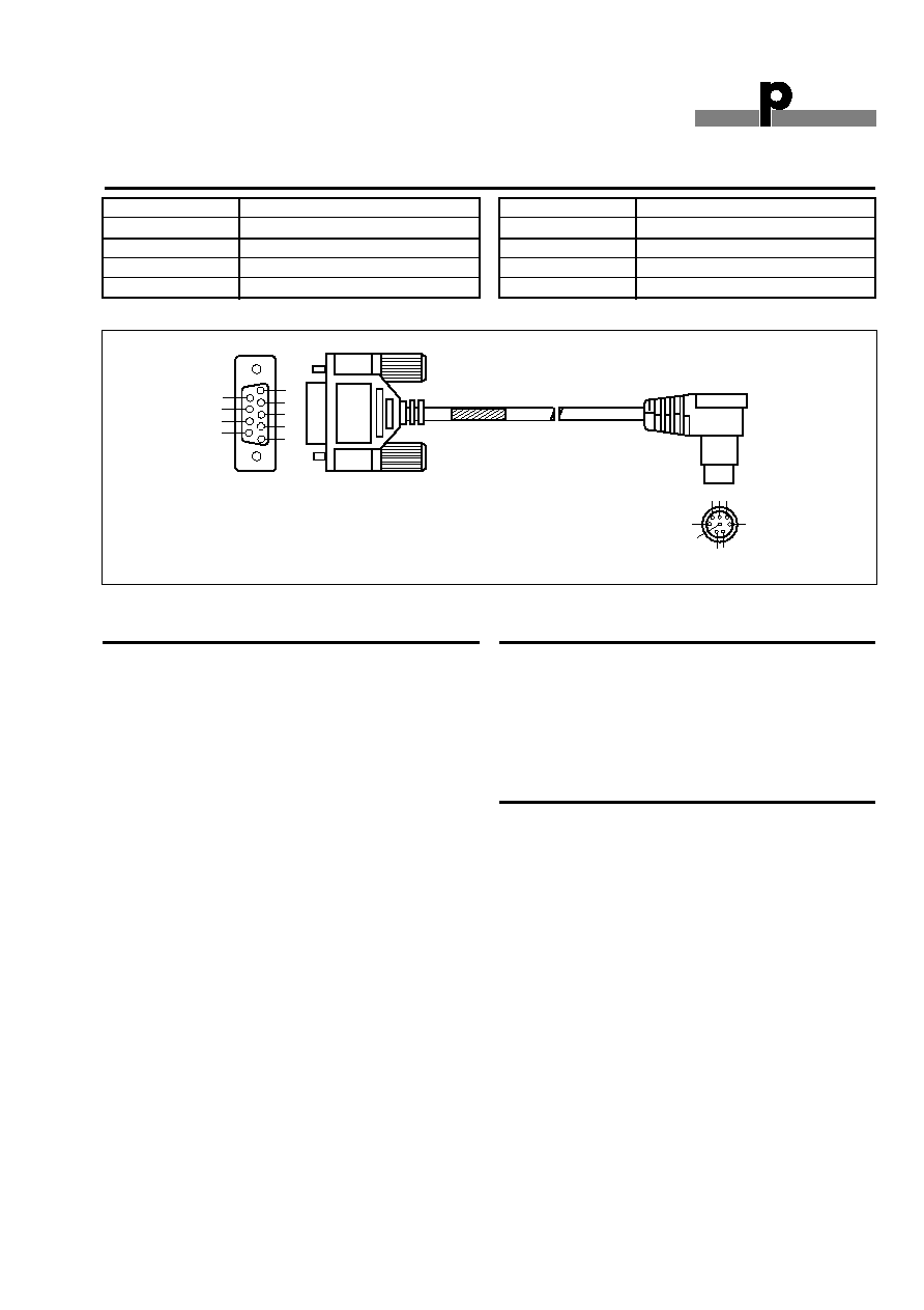
Accessories
Type MicroLogix
Cable Sub-D 9M/8 mini Din
RS-232-AB1
Type SLC
Cable Sub-D 9M/9M
RS-232-AB2
Additional Information
Scope of supply
1 x Master Module
G3496 0006 700
Pin Assignment
9
8
7
6
5
4
3
2
1
9-pin D-shell
8-pin Mini Din
6 7 8
3
4
1 2
5
G 3496 0006
DMM G34960006
Allen Bradley PLC type MicroLogix
9P D-SUB Male
8-pin mini-DIN Male
1 (Tx)
4 (Rxd)
9 (Rx)
7 (Txd)
5 (GND)
2 (GND)
DMM G34960006
Allen Bradley PLC type SLC
9P D-SUB Male
9-pin D-SUB Male
1 (Tx)
2 (Rxd)
9 (Rx)
3 (Txd)
5 (GND)
5 (GND)