Du line
Æ
Fieldbus
Installationbus
Specifications are subject to change without notice (05.05.03)
1
Dupline
Æ
is a registered trademark. A product of the CARLO GAVAZZI Group
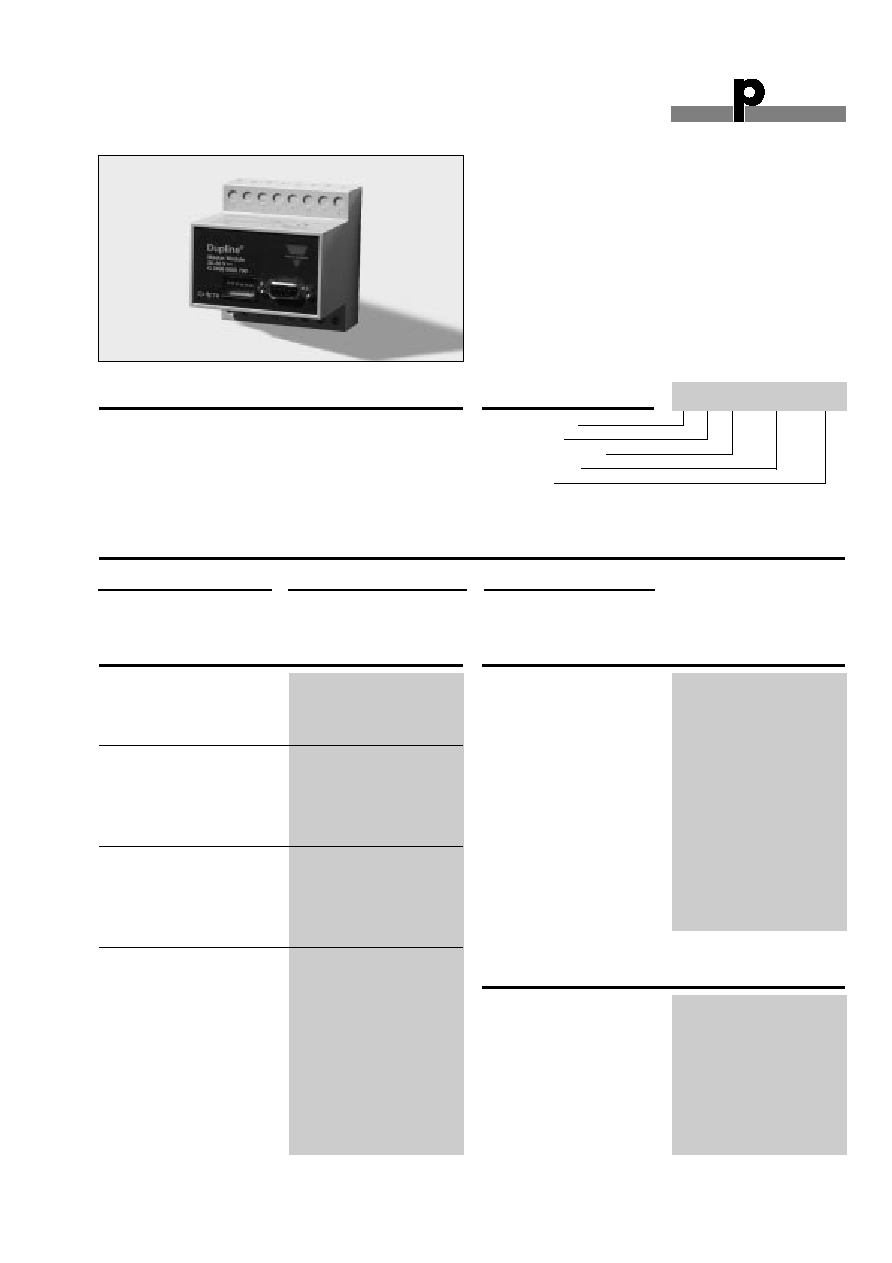
Type: Dupline
Æ
H4-Housing
Combined module
Interface type
DC supply
∑ Interface for Koyo PLC with the function of a Master
∑ Plug and play: Automatic communication with specific
PLC/Controllers
∑ Built-in normal Dupline
Æ
Channel Generator
∑ 128 I/O's and DC power supply on 3 wires
∑ RS232/RS422/RS485 port for interfacing to control
system
∑ Split-I/O mode selectable (128 inputs and 128 outputs)
∑ LED-indications for supply, Dupline
Æ
carrier and Com-
port TX
∑ Galvanically isolated Com-port supplied by internal
DC/DC converter
Product Description
Ordering Key
G 3496 0008 is designed as a
cost-effective solution for
interfacing Dupline
Æ
I/O's to
the Koyo DL05 Micro PLC
family. It performs three func-
tions: Dupline
Æ
channel gene-
rator, power supply synchro-
nization (enables 3-wire sys-
tem with supply) and
RS232/RS422/RS485 inter-
face.
Type Selection
Supply
PLC Interface Conformance
Ordering no.
20-30 VDC
DL05 Micro PLC family
G 3496 0008 700
G 3496 0008 700
Input/Output Specifications
Dupline
Æ
Plug & Play Master Module
Interface for Koyo PLC
Power Output
Output voltage
20-30 VDC (pulsating)
Output current
< 3.0 A @ 50∞C
Short circuit protection
4 A quick acting fuse
Output voltage drop
< 1.0 V
Dupline
Æ
carrier
Output voltage
8.2 V (pulsating)
Current
< 60 mA
Short circuit protection
Yes
Scan time
128 channels
132.2 ms
64 channels
69.8 ms
Communication Port
Standard
RS232/RS422/RS485
Connection
9 pole female Sub-D
Dielectric voltage
Com-port - Dupline
Æ
1 kVAC (rms)
Protocol
Modbus-RTU (function
code 01 and 15)
Channel Configuration in PLC
Baud rate
9600
Data bits
8
Start bit
1
Stop bit
1
Parity
None
Flow-control
None
Device no.
1
Type G 3496 0008
Input/Output Specifications (Cont.)
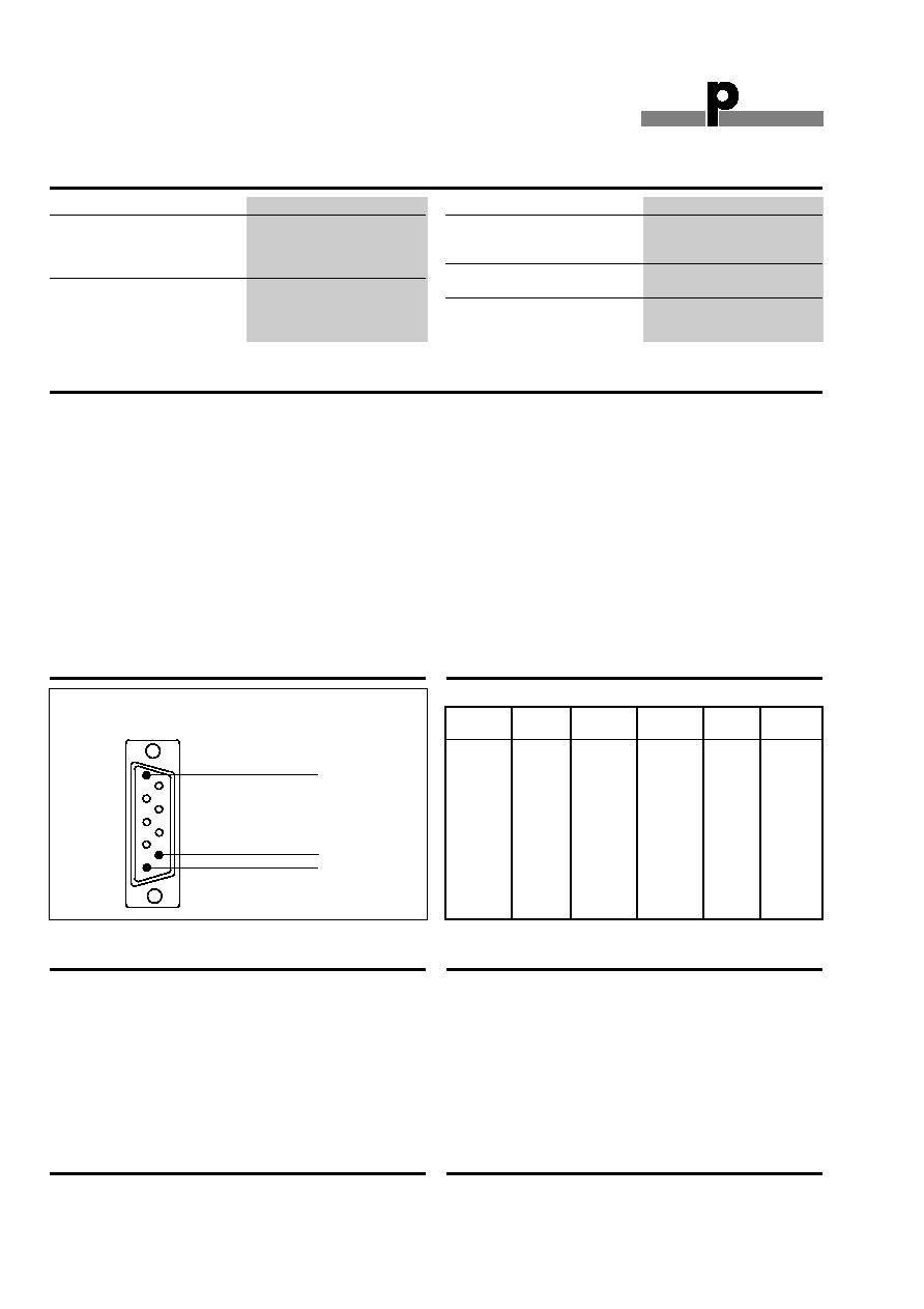
Pin assignment
2-wire RS485
S/R Data line + (B)
3
S/R Data line ≠ (A)
8
GND
5
4-wire RS485/RS422
R Data line + (B)
3
R Data line - (A)
8
S Data line + (B)
2
S Data line - (A)
7
Direction
4 (Connect pin 5 to GND
when using 4-wire com.)
RS232
TX
1
RX
9
GND
5
Supply Specifications
Power supply
Overvoltage cat. III
(IEC 60664)
Operational voltage (V
in
)
20-30 VDC
Reverse polarity protection
None
Current consumption
< 150 mA + Power load
Power dissipation
< 5 W
Transient protection voltage
800 V
Dielectric voltage
Supply ≠ Dupline
Æ
None
Supply ≠ Com-port
1 kVAC (rms)
Power ON delay
2 s
Indication for
Com-port TX
LED, red
Supply ON
LED, green
Dupline
Æ
carrier
LED, yellow
Environment
Pollution degree
2 (IEC 60664)
Operating temperature
0∞ to +50∞C (+32∞ to +122∞F)
Storage temperature
-50∞ to +85∞C (-58∞ to +185∞F)
Du line
Æ
Fieldbus
Installationbus
2
Specifications are subject to change without notice (12.01.01)
Dupline
Æ
is a registered trademark. A product of the CARLO GAVAZZI Group
Mode of Operation
The Dupline
Æ
Master Module
(DMM) controls a 3-wire bus
with signal, DC-power and
common GND. The DMM is
connected to a standard DC-
supply, which it synchronizes
with the Dupline
Æ
carrier signal
before it is outputted to supply.
The synchronization is neces-
sary in order to enable the
Dupline
Æ
and DC-supply to
share the GND-wire.
The Dupline
Æ
Master Module is
a Dupline
Æ
Channel Generator
with the function of a master.
This means that the 128
Dupline
Æ
I/O's will be read/writ-
ten by the DMM and then sent
to the PLC.
The DMM can run in two dif-
ferent modes ≠ Normal mode
and split I/O mode. In Normal
mode, Dupline
Æ
operates as a
peer-to-peer system, where
the channel generator auto-
matically establishes a con-
nection between Dupline
Æ
inputs and Dupline
Æ
outputs
which are coded to the same
Dupline
Æ
address. If e.g. an
input coded for B5 is activat-
ed, the output(s) coded for B5
will also be activated.
Consequently, a Dupline
Æ
-out-
put can either be activated
through the output-data
received on DMM or by an
active Dupline
Æ
input coded
for the same Dupline
Æ
-
address. In "Split I/O" mode,
the channel generator treats
the Dupline
Æ
inputs and
Dupline
Æ
outputs indepen-
dently. If e.g. an input coded
for B5 is activated, the DMM
will make the information avail-
able for the PLC (like in normal
mode), but it will not automati-
cally activate the Dupline
Æ
out-
put(s) coded to B5. The
Dupline
Æ
outputs are con-
trolled exclusively through the
output data received from the
PLC. In this mode, up to 128
Dupline
Æ
inputs and 128
Dupline
Æ
outputs are available,
since an input and an output
coded to the same Dupline
Æ
address can operate indepen-
dently.
G 3496 0008
General Specifications
Humidity (non-condensing)
20 to 80%
Mechanical resistance
Shock
15 G (11 ms)
Vibration
2 G (6 to 55 Hz)
Dimensions
H4-Housing
Material
(See Technical Information)
Weight
100 g
Dip-Switch Setting
Memory Mapping
Dupline
Æ
Read
Write
Dupline
Æ
Read
Write
Channel
Channel
A1
C0
C200
E1
C40
C240
A2
C1
C201
F1
C50
C250
A3
C2
C202
G1
C60
C260
A4
C3
C203
H1
C70
C270
A5
C4
C204
I1
C100
C300
A6
C5
C205
J1
C110
C310
A7
C6
C206
K1
C120
C320
A8
C7
C207
L1
C130
C330
B1
C10
C210
M1
C140
C340
B8
C17
C217
N1
C150
C350
C1
C20
C220
O1
C160
C360
D1
C30
C230
P1
C170
C370
Table of the memory mapping to the PLC
Installation Hints
Slow flashing TX-LED
Polling without contact to Koyo PLC
Check the wiring.
Fast flashing TX-LED
Communication OK
No Dupline
Æ
Carrier-LED
Dupline
Æ
Short circuit.
Short circuit between the
two Dupline
Æ
wires.
Accessories
Cable Sub-D 9p M /6p Phone Plug
RS-232-KO1
Additional Information
Scope of supply
1 x Master Module
G3496 0008 700
Pin Assignment
1
9
8
7
6
5
4
3
2
4
3
1
Dupline Master Module
9p D-sub. Male
Koyo PLC, CPU Port
6p Phone Plug
Sw.4
On:
Split I/O Channel Generator Mode
(Receivers activated by the PLC)
Off:
Normal Dupline Monostable Channel
Generator Mode
Sw. 5
On:
64 Dupline
Æ
channels
Off:
128 Dupline
Æ
channels
Sw.6
On:
Maintain data on Dupline
Æ
in case of
communication failure
Off:
Clear data on Dupline
Æ
after 10 sec. of
communication failure